- English
- French
- German
- Portuguese
- Spanish
- Russian
- Japanese
- Korean
- Arabic
- Greek
- German
- Turkish
- Italian
- Danish
- Romanian
- Indonesian
- Czech
- Afrikaans
- Swedish
- Polish
- Basque
- Catalan
- Esperanto
- Hindi
- Lao
- Albanian
- Amharic
- Armenian
- Azerbaijani
- Belarusian
- Bengali
- Bosnian
- Bulgarian
- Cebuano
- Chichewa
- Corsican
- Croatian
- Dutch
- Estonian
- Filipino
- Finnish
- Frisian
- Galician
- Georgian
- Gujarati
- Haitian
- Hausa
- Hawaiian
- Hebrew
- Hmong
- Hungarian
- Icelandic
- Igbo
- Javanese
- Kannada
- Kazakh
- Khmer
- Kurdish
- Kyrgyz
- Latin
- Latvian
- Lithuanian
- Luxembou..
- Macedonian
- Malagasy
- Malay
- Malayalam
- Maltese
- Maori
- Marathi
- Mongolian
- Burmese
- Nepali
- Norwegian
- Pashto
- Persian
- Punjabi
- Serbian
- Sesotho
- Sinhala
- Slovak
- Slovenian
- Somali
- Samoan
- Scots Gaelic
- Shona
- Sindhi
- Sundanese
- Swahili
- Tajik
- Tamil
- Telugu
- Thai
- Ukrainian
- Urdu
- Uzbek
- Vietnamese
- Welsh
- Xhosa
- Yiddish
- Yoruba
- Zulu
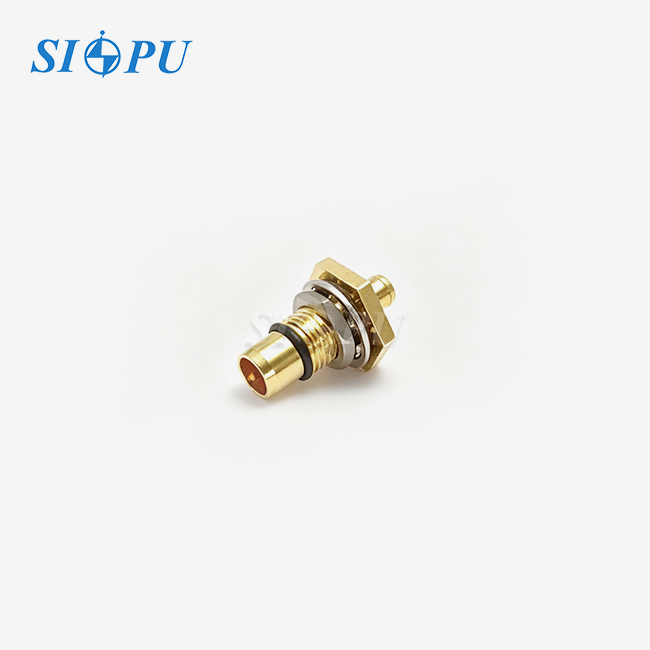
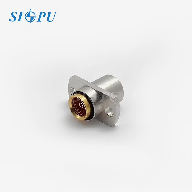
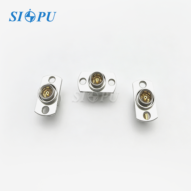
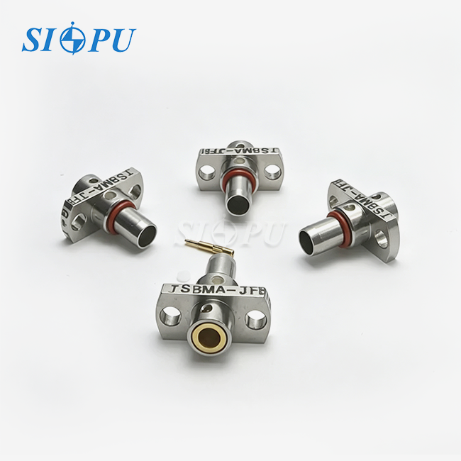
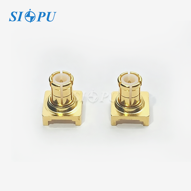
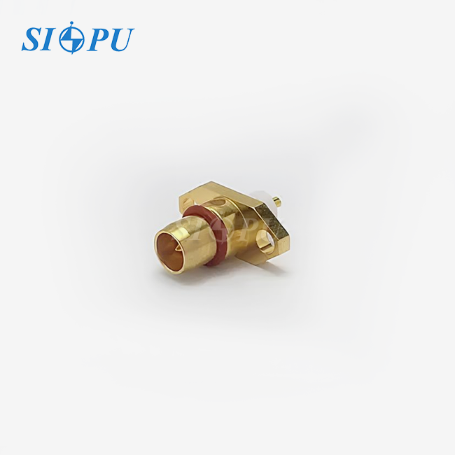
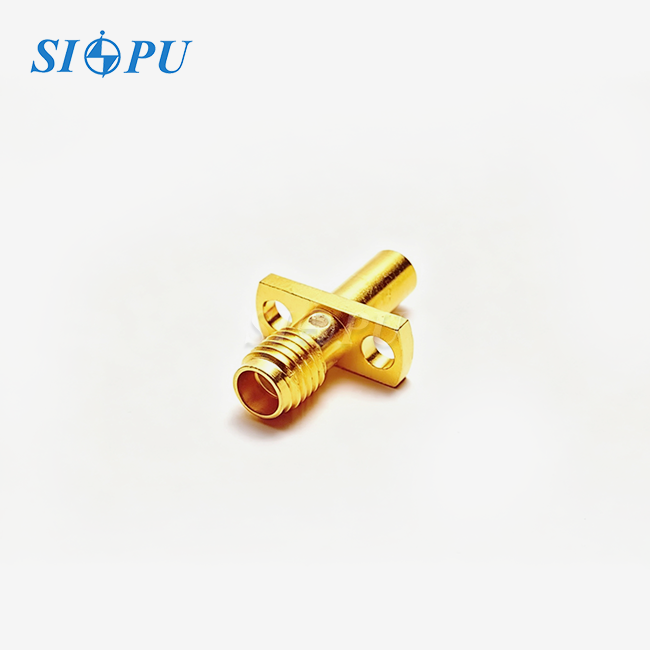
BMA Female Connector
Characteristic Impedance: 50 Ω
Connection Method: Floating push-on mating design
Mounting Method: Flange-mount structure for stable and secure installation
Cable Compatibility: Compatible with .047" semi-rigid cable series
Mechanical Performance: Robust construction with excellent vibration resistance
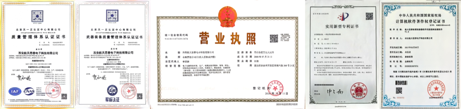
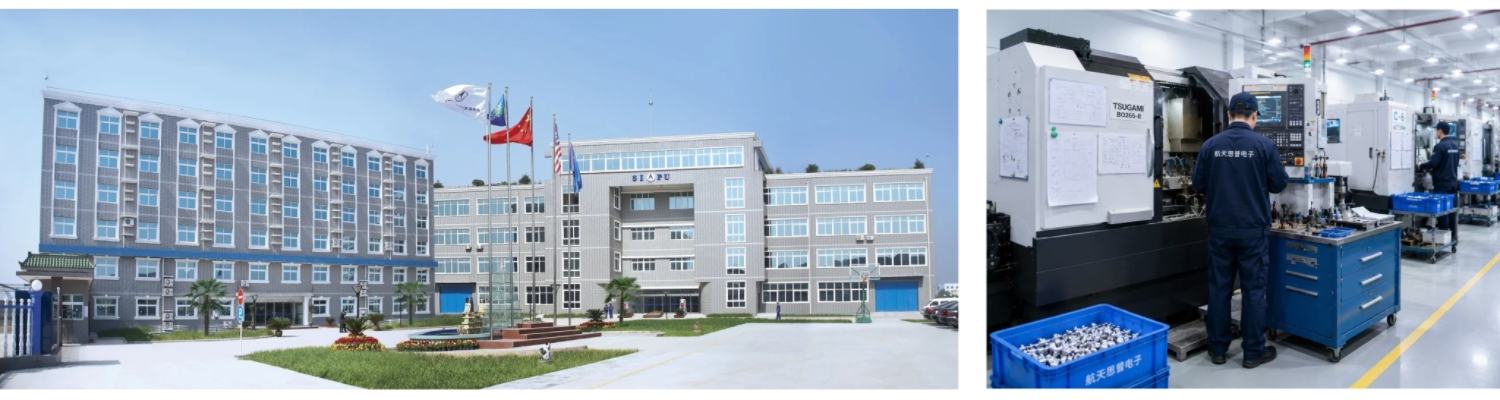
Manufacturing Capability: 30 years of manufacturing experience with fully equipped production facilities
Service Support: Product selection assistance and technical support available
BMA Female Connector | High-Performance Blind-Mate RF Solution
The BMA Female Connector, model SIPU-BMA-KFB1G-T, is a precision RF connector from SIPU RF Technology Co., Ltd. for high density modular applications. SIPU’s 50Ω characteristic impedance, up to 22 GHz operating frequency, blind-mate connection provides enterprise-grade performance, backed by more than 25 years of manufacturing experience.
This product has excellent electrical performance with VSWR < 1.15 + 0.012F(GHz) and insertion loss just ≤ 0.08√F(GHz) dB. Flange-mount design enables stable panel installation with ≥500 mating cycles endurance. Gold plated beryllium bronze center contacts provide maximum conductivity and the stainless steel outer conductor with passivation treatment provides high environmental resistance over a working temperature range of -65℃ to +125℃.
BMA Female Connector Specifications
| Parameter | Value |
|---|---|
| Electrical Performance | |
| Characteristic Impedance | 50Ω |
| Frequency Range | DC–22 GHz |
| VSWR | ≤ 1.15 + 0.012F(GHz) |
| Insertion Loss | ≤ 0.08√F(GHz) dB |
| Dielectric Withstanding Voltage | 1,000 V |
| Insulation Resistance | ≥ 5,000 MΩ |
| Contact Resistance (Center) | ≤ 3.0 mΩ |
| Contact Resistance (Outer) | ≤ 2.0 mΩ |
| Mechanical Properties | |
| Mating Cycles | ≥ 500 |
| Orientation | Straight |
| Interface Gender | Female |
| Environmental | |
| Operating Temperature | -65℃ to +125℃ |
| Materials | |
| Outer Conductor | Stainless steel, passivated |
| Center Conductor | Beryllium bronze, gold-plated |
| Dielectric | PTFE |
Key Performance Advantages
Blind-Mate Efficiency
The slide-on interface enables quick engagement without visual alignment. This design significantly reduces assembly time in high-density rack-and-panel configurations. Your production team benefits from repeatable connections that eliminate manual alignment errors.
Robust Mechanical Design
The flange mount construction provides exceptional stability for panel installations. Unlike threaded alternatives, this push-on mechanism withstands high-vibration environments while maintaining consistent electrical contact. The precision-machined housing ensures reliable performance across ≥500 mating cycles.
Superior Electrical Stability
Gold-plated beryllium bronze center contacts deliver minimal contact resistance (≤3.0 mΩ) for optimal signal transmission. The PTFE dielectric maintains low insertion loss across the full DC–22 GHz frequency spectrum. This combination ensures signal integrity in demanding RF applications.
Space-Optimized Architecture
The compact structure suits high-density RF modules where board space is critical. You can achieve greater component density compared to conventional threaded connectors. This space efficiency proves valuable in phased array systems and modular test equipment.
Environmental Resilience
Passivated stainless steel construction resists corrosion in harsh conditions. The wide operating temperature range (-65℃ to +125℃) supports aerospace and defense applications. Your systems maintain performance reliability through thermal cycling and extreme environmental exposure.
Application Scenarios
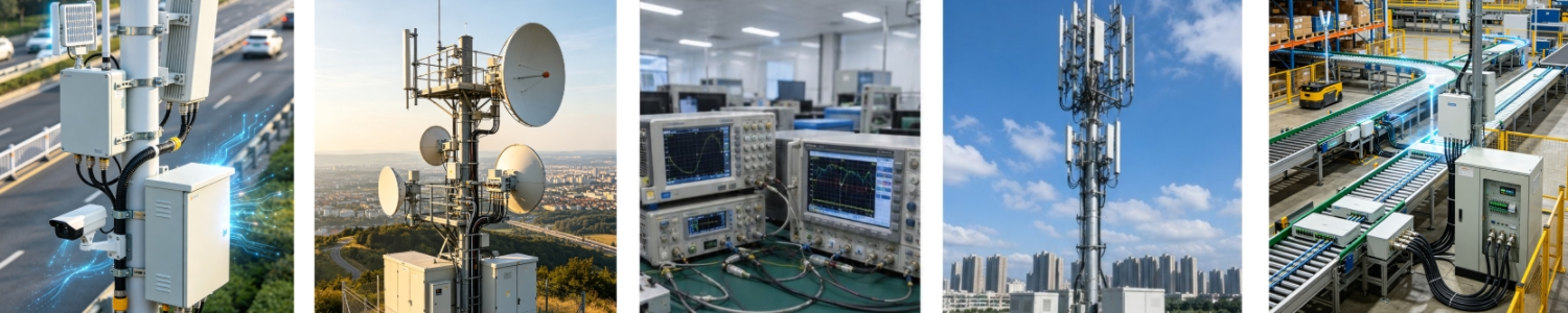
Phased Array Radar Systems
Defense and aerospace platforms rely on this connector for modular RF sub-assemblies. When you slide an array module into its rack, hundreds of connections engage simultaneously without manual intervention. The blind-mate capability ensures consistent phase alignment across all elements.
Automated Test Equipment
Semiconductor testing facilities use this solution in quick-change test heads. Your operators can reconfigure hardware rapidly without compromising delicate RF signal paths. The spring-loaded interface maintains stable electrical contact during high-speed automated switching.
Aerospace Avionics
Line Replaceable Units (LRUs) in aircraft communication systems demand connectors that withstand extreme G-forces. The flange-mount design provides secure attachment while the float capability compensates for thermal expansion. Your avionics maintain signal integrity throughout flight envelope extremes.
Quality Control & Testing
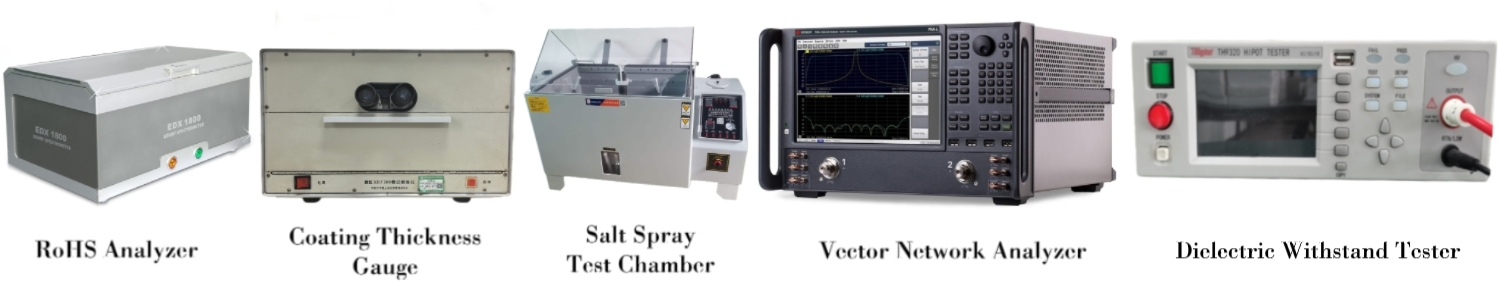
SIPU implements rigorous inspection protocols for every production batch. Each BMA Female Connector undergoes dielectric withstanding voltage testing using specialized equipment to verify 1,000V performance and ≥5,000 MΩ insulation resistance.
The company performs batch-level plating thickness and adhesion testing to ensure consistent contact quality. Every production lot receives RoHS environmental compliance verification. While VSWR and insertion loss are guaranteed through precision structural design, these electrical parameters are directly measured for cable assemblies and loads.
Frequently Asked Questions
Q: What misalignment does this connector tolerate?
A: The spring-loaded design typically accommodates axial and radial variations, maintaining electrical contact even when mounting surfaces experience thermal expansion or mechanical tolerances.
Q: Can I mate this with standard SMA connectors?
A: No, the slide-on BMA interface differs from threaded SMA designs. However, BMA-to-SMA adapters are available for test and integration purposes.
Q: Does installation require torque specifications?
A: No torque is necessary. The push-on engagement mechanism relies on controlled insertion force, making it ideal for automated assembly processes.
Q: Can you provide technical documentation?
A: Yes, SIPU supplies comprehensive datasheets, 2D/3D mechanical drawings, and performance data including VSWR curves and insertion loss measurements for your design validation.
Q: What industries benefit most from this connector?
A: Telecommunications infrastructure, aerospace defense systems, RF test equipment manufacturers, and research laboratories requiring high-density modular architectures gain significant advantages from this blind-mate solution.
Contact SIPU RF Technology
Ready to enhance your RF system reliability with our BMA Female Connector? Contact us at info@sipuconn.com to discuss your specific requirements or request samples for evaluation.
Contact us directly for customized solutions, quotations and long-term strategic cooperation.