- English
- French
- German
- Portuguese
- Spanish
- Russian
- Japanese
- Korean
- Arabic
- Greek
- German
- Turkish
- Italian
- Danish
- Romanian
- Indonesian
- Czech
- Afrikaans
- Swedish
- Polish
- Basque
- Catalan
- Esperanto
- Hindi
- Lao
- Albanian
- Amharic
- Armenian
- Azerbaijani
- Belarusian
- Bengali
- Bosnian
- Bulgarian
- Cebuano
- Chichewa
- Corsican
- Croatian
- Dutch
- Estonian
- Filipino
- Finnish
- Frisian
- Galician
- Georgian
- Gujarati
- Haitian
- Hausa
- Hawaiian
- Hebrew
- Hmong
- Hungarian
- Icelandic
- Igbo
- Javanese
- Kannada
- Kazakh
- Khmer
- Kurdish
- Kyrgyz
- Latin
- Latvian
- Lithuanian
- Luxembou..
- Macedonian
- Malagasy
- Malay
- Malayalam
- Maltese
- Maori
- Marathi
- Mongolian
- Burmese
- Nepali
- Norwegian
- Pashto
- Persian
- Punjabi
- Serbian
- Sesotho
- Sinhala
- Slovak
- Slovenian
- Somali
- Samoan
- Scots Gaelic
- Shona
- Sindhi
- Sundanese
- Swahili
- Tajik
- Tamil
- Telugu
- Thai
- Ukrainian
- Urdu
- Uzbek
- Vietnamese
- Welsh
- Xhosa
- Yiddish
- Yoruba
- Zulu
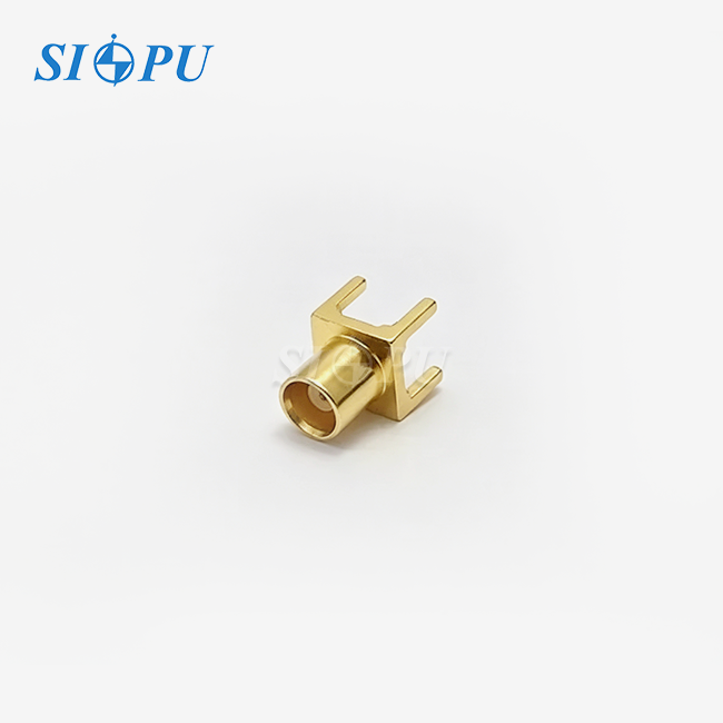
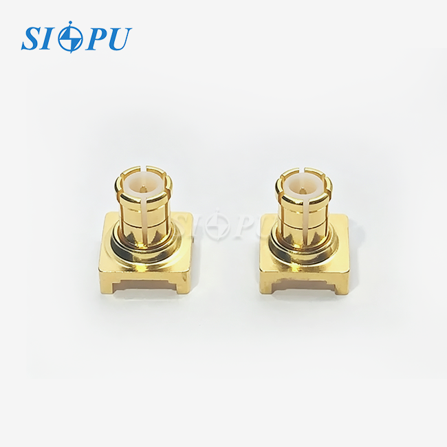
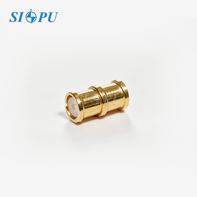
MCX Female PCB Mount 4-Pin Connector
Characteristic Impedance: 50 Ω
Size: Compact and lightweight design, ideal for high-density PCB layouts
Connection Method: Right-angle four-leg PCB mounting design with reliable soldering performance
High Frequency Performance: Stable electrical performance for reliable RF signal transmission
Manufacturing Capability: 30 years of manufacturing experience with customization support
Service Support: Customization and technical support available
MCX Female PCB Mount 4-Pin Connector – Precision RF Interconnect for Reliable Board-Level Integration
SIPU RF Technology introduces the MCX Female PCB Mount 4-Pin Connector (Model: SIPU-MCX-KWHD1) designed for high frequency applications that need a strong mechanical lock and reliable electrical performance. This right-angle connection is designed for DC to 6 GHz operation with a VSWR of ≤1.4 and an insertion loss of ≤0.1√F(GHz) dB. It contains four through-hole pins for excellent solder bond strength and vibration resistance.
The connector is constructed with gold plated brass outer conductors and gold plated beryllium copper center contacts, and PTFE dielectric, maintaining 50Ω impedance and operating in temperatures from -65°C to +125°C. Its small size allows for dense PCB layouts, providing 500 mating cycles and ≥1,000MΩ insulation resistance, making it suitable for space-constrained telephony, GPS modules and RF test equipment.
MCX Female PCB Mount 4-Pin Connector Specifications
| Parameter | Value |
|---|---|
| Model | SIPU-MCX-KWHD1 |
| Characteristic Impedance | 50Ω |
| Frequency Range | DC–6 GHz |
| VSWR | ≤1.4 |
| Insertion Loss | ≤0.1√F(GHz) dB |
| Dielectric Withstanding Voltage | 750V |
| Insulation Resistance | ≥1,000 MΩ |
| Contact Resistance (Center) | ≤4.0 mΩ |
| Contact Resistance (Outer) | ≤2.5 mΩ |
| Mating Cycles | 500 Cycles |
| Operating Temperature | -65°C to +125°C |
| Orientation | Right Angle |
| Interface Gender | Female |
| Outer Conductor Material | Brass (gold-plated) |
| Center Conductor Material | Beryllium Copper (gold-plated) |
| Dielectric Material | PTFE |
Key Design Features
Four-Pin Through-Hole Architecture
The four-pin interface to the PCB offers more solder joint strength than surface-mount options. This design provides far higher resilience to mechanical stress and vibration for reliable connections in difficult settings.
Each pin provides a solid electrical and mechanical connection to your board. This setup is particularly useful for applications that are often handled or transported.
Optimized for High-Volume Manufacturing
The connector’s uniform pin layout and standard form factor are advantageous for automated assembly processes. The pick and place machines can easily handle the component and save the manufacturing time and placement mistakes.
Your production team will be pleased with the predictable solder flow. The design is compatible with wave and reflow soldering procedures with the suitable thermal profiling.
Space-Efficient Footprint
Small form factor allows for dense component configurations without sacrificing on RF performance. With a right-angle orientation, signals are orientated parallel to the board providing maximum vertical headroom in enclosures.
This makes the connector particularly useful for miniaturised devices. And you can have tighter integration without sacrificing signal integrity throughout the whole 6 GHz bandwidth.
Controlled-Loss Signal Transmission
Gold plated contacts minimise insertion loss and keep contact resistance low during the 500 cycle life of the connection. The PTFE dielectric offers consistent electrical characteristics across the operational temperature range.”
Your signals degrade very little even in extreme thermal conditions. Such systems are important for dependability of RF communication systems and precision test equipment.
Manufacturing Quality Control
Electrical Performance Verification
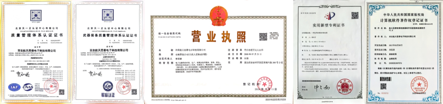
Every batch undergoes dielectric withstanding voltage testing and insulation resistance measurement using specialized equipment. These tests confirm the connector meets its 750V rating and ≥1,000 MΩ specification.
VSWR and insertion loss characteristics are guaranteed through precision mechanical design. Our engineering team validates these parameters during development to ensure consistent performance across production runs.
Plating Quality Assurance
Each production batch includes plating thickness and adhesion testing. We verify gold plating integrity to ensure long-term contact reliability and corrosion resistance.
RoHS compliance testing is conducted per batch to confirm environmental standards. You receive products that meet international regulations for hazardous substance restrictions.

Application Scenarios
The MCX Female PCB Mount 4-Pin Connector serves diverse industries requiring reliable board-level RF connections:
Wireless Communication Devices: Mobile infrastructure, radio modules, and antenna systems benefit from the connector's low-loss transmission and compact integration.
GPS Modules: Navigation equipment relies on the connector's stable phase performance and resistance to environmental stress during vehicle operation.
RF Test Equipment: Measurement systems require repeatable connections with minimal signal degradation across frequent mating cycles.
Industrial Control Systems: Factory automation and sensor networks utilize the connector's robust mechanical design for reliable long-term operation.
The right-angle configuration suits applications where cable routing must run parallel to the board surface. This orientation simplifies enclosure design and reduces overall system profile.

Packaging
SIPU packages connectors in anti-static trays or tape-and-reel formats suitable for automated assembly lines. Each package includes product identification labels and handling instructions to ensure component integrity during storage and transportation.
Frequently Asked Questions
Q: Why should I choose the four-pin through-hole design over surface-mount options?
A: The four-pin through-hole configuration provides superior mechanical anchoring to your PCB. This design offers significantly higher shear strength and resistance to torque compared to surface-mount equivalents, making it essential for applications subject to vibration or frequent connector engagement.
Q: What soldering processes are compatible with this connector?
A: The connector accommodates both wave and reflow soldering. We recommend controlled thermal profiles to protect the PTFE dielectric and ensure precise alignment with your PCB footprint during assembly.
Q: How does the snap-on coupling mechanism perform under mechanical stress?
A: The MCX interface provides a retention force of approximately 10N (2.3 lbs), maintaining secure engagement during normal operation while allowing intentional manual disconnection when needed.
Q: Can you provide technical documentation for design integration?
A: Yes, we supply datasheets, 2D/3D structural drawings, and performance parameter reports including VSWR and insertion loss data upon request.
Q: What lead times should I expect for volume orders?
A: Standard products ship within 72 hours from stock. Custom configurations or specialized plating requirements may extend delivery by 1-2 weeks depending on specification complexity.

Contact Us
Our MCX Female PCB Mount 4-Pin Connector's team at SIPU RF Technology is available to discuss your specific requirements and provide technical support. Reach out to info@sipuconn.com for quotations, samples, or application assistance.
Contact us directly for customized solutions, quotations and long-term strategic cooperation.