- English
- French
- German
- Portuguese
- Spanish
- Russian
- Japanese
- Korean
- Arabic
- Greek
- German
- Turkish
- Italian
- Danish
- Romanian
- Indonesian
- Czech
- Afrikaans
- Swedish
- Polish
- Basque
- Catalan
- Esperanto
- Hindi
- Lao
- Albanian
- Amharic
- Armenian
- Azerbaijani
- Belarusian
- Bengali
- Bosnian
- Bulgarian
- Cebuano
- Chichewa
- Corsican
- Croatian
- Dutch
- Estonian
- Filipino
- Finnish
- Frisian
- Galician
- Georgian
- Gujarati
- Haitian
- Hausa
- Hawaiian
- Hebrew
- Hmong
- Hungarian
- Icelandic
- Igbo
- Javanese
- Kannada
- Kazakh
- Khmer
- Kurdish
- Kyrgyz
- Latin
- Latvian
- Lithuanian
- Luxembou..
- Macedonian
- Malagasy
- Malay
- Malayalam
- Maltese
- Maori
- Marathi
- Mongolian
- Burmese
- Nepali
- Norwegian
- Pashto
- Persian
- Punjabi
- Serbian
- Sesotho
- Sinhala
- Slovak
- Slovenian
- Somali
- Samoan
- Scots Gaelic
- Shona
- Sindhi
- Sundanese
- Swahili
- Tajik
- Tamil
- Telugu
- Thai
- Ukrainian
- Urdu
- Uzbek
- Vietnamese
- Welsh
- Xhosa
- Yiddish
- Yoruba
- Zulu
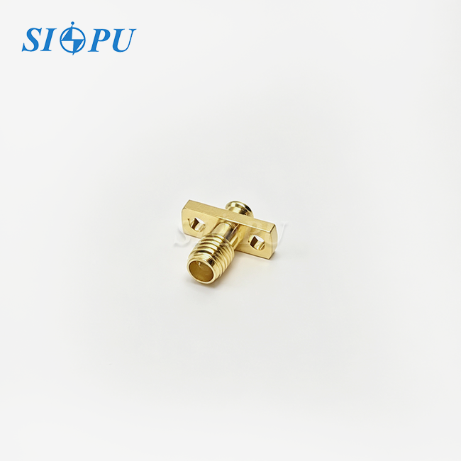
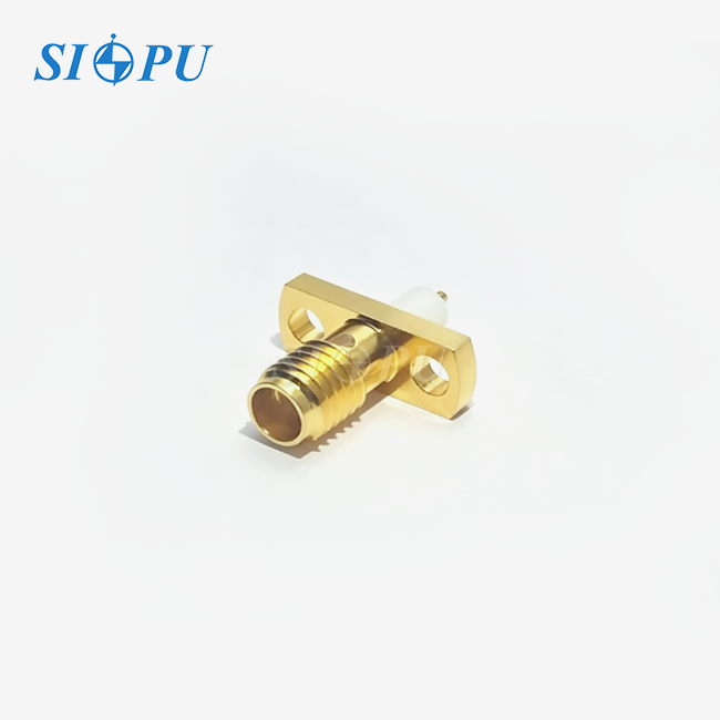
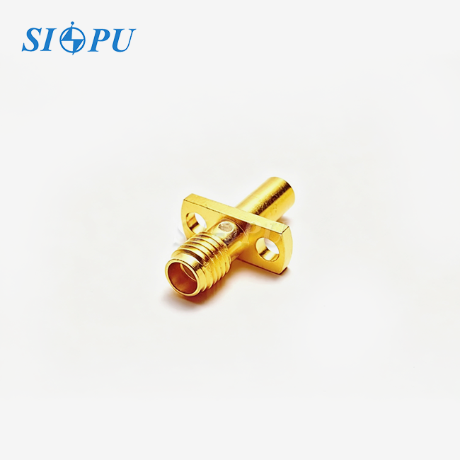
SMA Female 2-Hole Flange Microstrip Connector
Characteristic Impedance: 50 Ω
Mounting Method: Two-hole flange microstrip design for high-precision installation
High Frequency Performance: Supports frequencies up to 18 GHz
Size: Compact design suitable for high-density microstrip layouts
Manufacturing Capability: Equipped with advanced CNC machining and RF testing equipment
Custom Service: Custom design and small-batch prototype support available
SMA Female 2-Hole Flange Microstrip Connector – High-Precision RF Interface for PCB Integration
SIPU RF Technology SMA Female 2-Hole Flange Microstrip Connector provides enterprise level performance for demanding RF applications which need direct PCB microstrip transitions. The connection is MIL and IEC certified and has a frequency range of DC to 18 GHz with a VSWR of ≤1.05 + 0.012F (GHz) and insertion loss of ≤0.05√F (GHz) dB. The tiny dual-hole flange design provides an optimal mounting footprint while retaining mechanical stability and electrical integrity.
The connection has gold-plated brass outer conductors and beryllium bronze core contacts with PTFE dielectric insulation. Rated for over 500 mating cycles and designed to operate from -65oC to +125oC, it has quality manufacture with dependable performance for telecommunications, aerospace and test equipment applications.
What Is an SMA Female 2-Hole Flange Microstrip Connector?
The specialised RF coaxial interface provides a direct transfer from coaxial cable settings to microstrip or stripline PCB circuits. This is different from the usual SMA connections that include a longer terminal pin for surface mount or through-hole soldering straight to microstrip traces.
The dual-hole flange configuration addresses space constraints in high-density electronic assemblies. Where traditional 4-hole flanges prove too bulky, this compact design enables secure mounting in crowded enclosures without compromising mechanical stability.
By providing a controlled ground path through the flange, the connector minimizes parasitic capacitance and inductance at the critical PCB transition point. This design preserves signal integrity in high-frequency microwave assemblies where impedance discontinuities can degrade performance.
Technical Specifications
| Parameter | Value |
|---|---|
| Model | SIPU-SMA-KFD46T |
| Characteristic Impedance | 50Ω |
| Frequency Range | DC–18 GHz |
| VSWR | ≤1.05 + 0.012F (GHz) |
| Insertion Loss | ≤0.05√F (GHz) dB |
| Dielectric Withstanding Voltage | 1,000 V |
| Insulation Resistance | ≥5,000 MΩ |
| Contact Resistance (Center) | ≤3.0 mΩ |
| Contact Resistance (Outer) | ≤2.0 mΩ |
| Mating Cycles | ≥500 |
| Microstrip Interface Size | φ1.3 × 3 mm |
| Operating Temperature | -65℃ to +125℃ |
| Outer Conductor Material | Brass, Gold Plated |
| Center Conductor Material | Beryllium Bronze, Gold Plated |
| Dielectric Material | PTFE |
| Mounting Style | PCB Microstrip, Dual-Hole Flange |
Key Performance Features
Superior Electrical Performance
Supporting frequencies up to 18 GHz, this connector meets medium- to high-frequency signal transmission requirements with precision. The characteristic impedance remains stable at 50Ω throughout the operational band.
Low insertion loss ensures minimal signal degradation across the frequency range. The VSWR specification guarantees excellent impedance matching, reducing reflections that can compromise system performance.
Optimized Microstrip Integration
The specialized microstrip configuration enables direct PCB integration while minimizing signal path loss. The φ1.3 × 3 mm interface dimension provides reliable contact with PCB traces.
This design eliminates the need for additional transition components. You achieve cleaner signal paths and reduced assembly complexity in your RF circuits.
Robust Mechanical Design
The dual-hole flange delivers secure mounting in space-constrained applications. With over 500 mating cycles, the connector maintains consistent performance throughout its service life.
Blue mounting features allow quick visual identification during assembly and maintenance. This practical design element reduces installation errors in complex systems.
Premium Materials and Construction
Gold-plated brass outer conductors provide excellent conductivity and corrosion resistance. Beryllium bronze center contacts offer superior spring force retention and electrical performance.
PTFE dielectric material ensures low loss and stable performance across temperature extremes. The combination delivers reliable operation from -65℃ to +125℃.
Quality Control Process
SIPU implements rigorous quality verification throughout manufacturing to ensure consistent performance. Each production batch undergoes comprehensive inspection protocols.

Electrical Testing
Dielectric withstanding voltage testing uses specialized equipment to verify 1,000V capability. Insulation resistance measurements confirm values exceed 5,000 MΩ specifications.
Contact resistance verification ensures center and outer contacts meet their respective thresholds. These tests guarantee reliable signal transmission across all frequency bands.
Plating Quality Verification
Every batch undergoes plating thickness measurement to verify gold layer specifications. Plating adhesion testing confirms the coating withstands mechanical stress and environmental exposure.
RoHS environmental compliance testing ensures all materials meet international standards. This commitment protects both your products and the environment.
Dimensional Precision
Precision measurement equipment verifies critical dimensions including flange hole spacing and microstrip interface geometry. Tolerances remain within strict limits to ensure proper PCB mating.
These controls eliminate mechanical stress on PCB assemblies during installation. You receive connectors that mount reliably without requiring special handling procedures.

Application Scenarios
Telecommunications Infrastructure
In 5G base stations and beamforming antenna arrays, this connector facilitates high-density signal routing from power amplifier boards to distribution networks. The compact footprint supports dense channel configurations.
The microstrip design enables efficient transitions in small cell equipment where space comes at a premium. Your systems maintain signal integrity while maximizing component density.
Aerospace and Defense Systems
Phased-array antenna modules rely on the dual-hole flange for secure mechanical anchoring under high-vibration conditions. The design withstands launch forces while maintaining electrical performance.
Satellite communication transceivers benefit from the compact profile in massive MIMO configurations. The SMA Female 2-Hole Flange Microstrip Connector delivers stable performance in extreme environments where failure is not an option.
Test and Measurement Equipment
Vector network analyzers and high-frequency signal generators incorporate these connectors on front panels for microstrip-based device testing. Phase stability remains consistent across thousands of mating cycles.
Laboratory instruments require repeatable performance across varying temperatures. This connector maintains calibration accuracy in demanding measurement applications.

Frequently Asked Questions
Q: How does the 2-hole flange compare to 4-hole versions for mounting security?
A: The 2-hole flange provides adequate mechanical stability for most applications while offering a smaller footprint. For high-vibration environments like aerospace platforms, evaluate your specific shock and vibration requirements to determine suitability.
Q: Can this connector handle frequencies above 18 GHz?
A: This model is optimized for DC to 18 GHz operation. For higher frequency requirements, consult our engineering team about alternative connector designs with extended bandwidth capabilities.
Q: What PCB trace width works best with the microstrip interface?
A: The φ1.3 × 3 mm interface dimension is designed for standard 50Ω microstrip traces. Your PCB designer should calculate trace width based on substrate dielectric constant and thickness for proper impedance matching.
Q: How do I ensure proper ground connection with the flange?
A: Clean the mounting surface thoroughly and ensure flat contact between the flange and your chassis or PCB ground plane. Proper torque during installation creates the low-impedance ground path essential for performance.

Contact Us for Your RF Connectivity Needs
Contact our SMA Female 2-Hole Flange Microstrip Connector's team at info@sipuconn.com for product specifications, samples, or technical consultation.
Contact us directly for customized solutions, quotations and long-term strategic cooperation.