- English
- French
- German
- Portuguese
- Spanish
- Russian
- Japanese
- Korean
- Arabic
- Greek
- German
- Turkish
- Italian
- Danish
- Romanian
- Indonesian
- Czech
- Afrikaans
- Swedish
- Polish
- Basque
- Catalan
- Esperanto
- Hindi
- Lao
- Albanian
- Amharic
- Armenian
- Azerbaijani
- Belarusian
- Bengali
- Bosnian
- Bulgarian
- Cebuano
- Chichewa
- Corsican
- Croatian
- Dutch
- Estonian
- Filipino
- Finnish
- Frisian
- Galician
- Georgian
- Gujarati
- Haitian
- Hausa
- Hawaiian
- Hebrew
- Hmong
- Hungarian
- Icelandic
- Igbo
- Javanese
- Kannada
- Kazakh
- Khmer
- Kurdish
- Kyrgyz
- Latin
- Latvian
- Lithuanian
- Luxembou..
- Macedonian
- Malagasy
- Malay
- Malayalam
- Maltese
- Maori
- Marathi
- Mongolian
- Burmese
- Nepali
- Norwegian
- Pashto
- Persian
- Punjabi
- Serbian
- Sesotho
- Sinhala
- Slovak
- Slovenian
- Somali
- Samoan
- Scots Gaelic
- Shona
- Sindhi
- Sundanese
- Swahili
- Tajik
- Tamil
- Telugu
- Thai
- Ukrainian
- Urdu
- Uzbek
- Vietnamese
- Welsh
- Xhosa
- Yiddish
- Yoruba
- Zulu
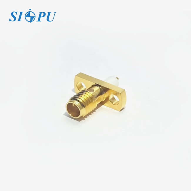
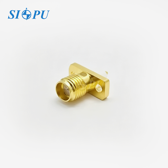
SMA Female Flange Mount Microstrip
Characteristic Impedance: 50 Ω
Connection Method: Flange-mount microstrip design
Size: Compact and optimized for high-density microstrip applications
Manufacturing Capability: 30 years of manufacturing experience with mature production processes
Service Support: Product selection assistance and technical support available
After-Sales Service: Quality assurance with installation guidance and technical support
SMA Female Flange Mount Microstrip - High-Performance RF Connector
SIPU RF Technology designs and manufactures SMA Female Flange Mount Microstrip connections that are precisely manufactured for mission critical applications. Our model SIPU-SMA-KWFD5 runs across DC-18 GHz with excellent electrical performance: insertion loss <=0.08√F(GHz)dB and VSWR <=1.06+0.015√F(GHz) The PTFE dielectric, gold-plated beryllium bronze center conductor, and gold-plated brass outer conductor of this connection provide excellent signal integrity. The 50$\Omega$ characteristic impedance also facilitates integration with microstrip PCB designs. Our product offers consistent performance in harsh settings from -65℃ to +125℃ with 1,000V dielectric withstanding voltage and ≥5,000MΩ insulation resistance. This straight-orientation female connection is rated for 500 mating cycles and offers the electrical accuracy and mechanical stability your RF systems need.
Product Features & Design Excellence
The right-angle flange mounting structure offers superior mechanical stability compared with conventional straight PCB-mount connectors. The connector is fixed directly to the chassis housing, reducing stress exerted on sensitive solder joints during assembly and long-term operation. It also addresses the connection requirement for lateral connector interfaces.
The microstrip interface is optimised for impedance matching for flat transmission lines on your PCB. This design minimises reflections, maintains a constant 50Ω impedance throughout the transition from coax to microstrip and is important to signal integrity at microwave frequencies.
Gold coating on the center and outside conductors assures long-term dependability and oxidation resistance. The beryllium bronze center contact retains good spring properties throughout the connector’s 500-cycle life.
The PTFE dielectric material has steady electrical characteristics across the whole temperature range. This quality insulator minimises signal loss and provides constant performance whether your application is in the arctic or in a high-temperature industrial setting.
SMA Female Flange Mount Microstrip Specifications
| Parameter | Specification |
|---|---|
| Model | SIPU-SMA-KWFD5 |
| Characteristic Impedance | 50Ω |
| Frequency Range | DC–18 GHz |
| Insertion Loss | ≤0.08√F(GHz)dB |
| VSWR | ≤1.06+0.015F(GHz) |
| Dielectric Withstanding Voltage | 1,000 V |
| Insulation Resistance | ≥5,000MΩ |
| Center Contact Resistance | ≤3.0mΩ |
| Outer Contact Resistance | ≤2.0mΩ |
| Mating Cycles | 500 cycles |
| Operating Temperature | -65℃ to +125℃ |
| Orientation | Right Angle |
| Interface Gender | Female |
| Outer Conductor Material | Brass, Gold Plated |
| Center Conductor Material | Beryllium Bronze, Gold Plated |
| Dielectric Material | PTFE |
Quality Control Process
Your connector undergoes rigorous inspection before shipment. Each batch receives comprehensive testing to verify dimensional accuracy, plating quality, and electrical performance.

We perform dielectric withstanding voltage testing and insulation resistance measurement on every production batch using precision test equipment. These tests confirm the connector meets the specified 1,000V dielectric strength and exceeds 5,000MΩ insulation resistance.
Plating thickness verification ensures gold coating meets industry standards for corrosion resistance and contact reliability. We measure plating depth and test adhesion strength to guarantee long-term performance in your application.
RoHS compliance testing is conducted on each production batch. This environmental screening confirms your connector contains no restricted substances, meeting global regulatory requirements for electronic components.

Application Scenarios
Your aircraft and defence equipment benefit from a strong flange mount under severe vibration and shock loads. The mechanical decoupling preserves the RF signal route and the microstrip interface ensures signal integrity in radar modules and communication equipment.
These connectors are used in telecommunications infrastructure to link the coaxial feedlines to the RF circuitry on the PCBs. The flange mount offers the mechanical stability required for exterior installations in 5G base stations and power amplifiers, while the microstrip design provides reduced insertion loss.
Repeatable connections are required for test and measurement applications spanning thousands of cycles . The flange mount design locates the connection in the exact place in your test fixture. The microstrip interface enables immediate hook-up to calibration standards and high frequency probes.
This connection offers the temperature stability and mechanical robustness needed for industrial electronics in severe environments. Your equipment delivers constant RF performance from -65℃ to +125℃ with no deterioration in signal.

Installation & PCB Integration
Good PCB layout will get the most performance from your microstrip connection. Calculate your PCB trace width to maintain 50Ω impedance up to the connector interface given the substrate dielectric constant and thickness.
The SMA Female Flange Mount Microstrip holes are for mechanical connection to your chassis. Select adequate fasteners that give solid pressure, without over-torquing, which might distort the flange or produce ground loop concerns.
Align the connection so the microstrip pin makes good contact with your PCB trace. As the air gap is minimised and properly aligned, the VSWR performance degradation due to impedance discontinuities may be minimised.
When designing your panel arrangement, remember the straight orientation of the connection. Provide appropriate distance for mating cables and keep away from other RF parts for unintended coupling.
Frequently Asked Questions
Q: What advantages does the microstrip interface provide over standard PCB launch connectors?
A: The microstrip design optimizes impedance matching for planar transmission lines, reducing signal reflections and insertion loss at the coaxial-to-PCB transition point, particularly important above 6 GHz.
Q: How does the flange mount improve reliability compared to direct PCB mounting?
A: Flange mounting mechanically isolates the connector from PCB flexure and thermal stress, preventing solder joint fatigue and maintaining consistent electrical performance throughout the product lifecycle.
Q: Can this connector withstand outdoor telecommunications environments?
A: Yes, with its -65℃ to +125℃ operating range, gold-plated contacts for corrosion resistance, and robust mechanical design, this connector performs reliably in outdoor base station applications.
Q: What mating connector type should I use with this female SMA flange mount?
A: Use standard SMA male connectors with compatible thread coupling. Ensure the mating connector meets the same 50Ω impedance and frequency specifications for optimal performance.
Q: How do I verify the connector maintains specification after installation?
A: Measure VSWR and insertion loss across your operating frequency range using a vector network analyzer. Compare results against the specified performance curves to confirm proper installation.

Contact Us for Your RF Solution
SIPU RF Technology offers expert technical support and rapid delivery for your SMA Female Flange Mount Microstrip requirements. Contact our engineering team at info@sipuconn.com
Contact us directly for customized solutions, quotations and long-term strategic cooperation.