- English
- French
- German
- Portuguese
- Spanish
- Russian
- Japanese
- Korean
- Arabic
- Greek
- German
- Turkish
- Italian
- Danish
- Romanian
- Indonesian
- Czech
- Afrikaans
- Swedish
- Polish
- Basque
- Catalan
- Esperanto
- Hindi
- Lao
- Albanian
- Amharic
- Armenian
- Azerbaijani
- Belarusian
- Bengali
- Bosnian
- Bulgarian
- Cebuano
- Chichewa
- Corsican
- Croatian
- Dutch
- Estonian
- Filipino
- Finnish
- Frisian
- Galician
- Georgian
- Gujarati
- Haitian
- Hausa
- Hawaiian
- Hebrew
- Hmong
- Hungarian
- Icelandic
- Igbo
- Javanese
- Kannada
- Kazakh
- Khmer
- Kurdish
- Kyrgyz
- Latin
- Latvian
- Lithuanian
- Luxembou..
- Macedonian
- Malagasy
- Malay
- Malayalam
- Maltese
- Maori
- Marathi
- Mongolian
- Burmese
- Nepali
- Norwegian
- Pashto
- Persian
- Punjabi
- Serbian
- Sesotho
- Sinhala
- Slovak
- Slovenian
- Somali
- Samoan
- Scots Gaelic
- Shona
- Sindhi
- Sundanese
- Swahili
- Tajik
- Tamil
- Telugu
- Thai
- Ukrainian
- Urdu
- Uzbek
- Vietnamese
- Welsh
- Xhosa
- Yiddish
- Yoruba
- Zulu
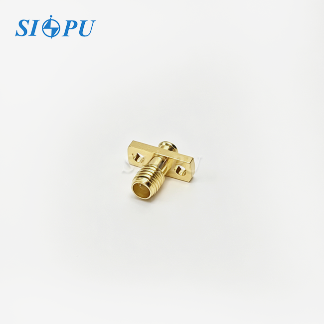
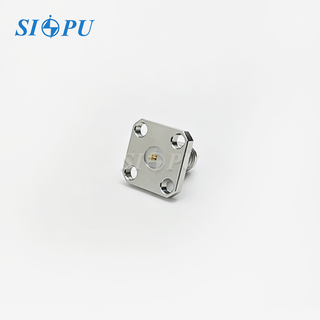
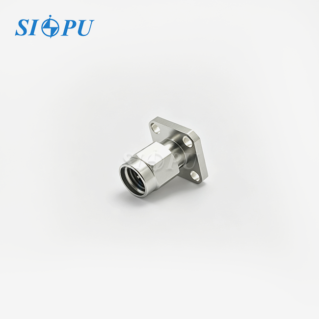
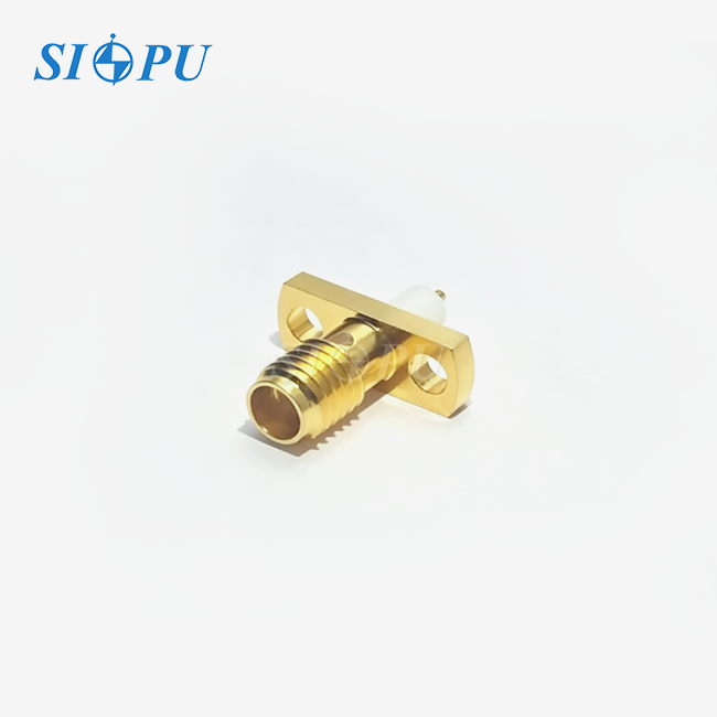
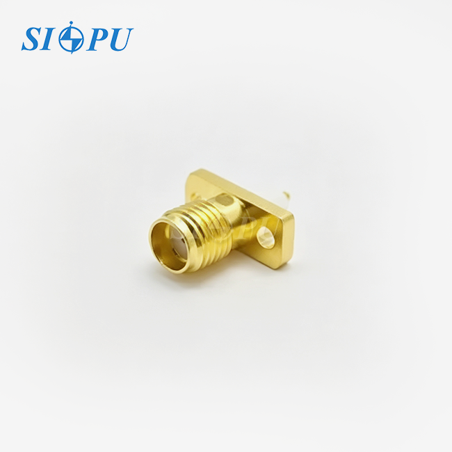
SMA Female 4-Hole Flange Microstrip Connector 18GHz
Characteristic Impedance: 50 Ω
Mounting Method: Four-hole flange microstrip PCB-mount design
High Frequency Performance: Supports frequencies up to 18 GHz
Manufacturing Capability: Equipped with precision CNC machining and RF testing facilities
Service Support: Product selection assistance and technical support available
Compliance Standards: Compliant with international standards including RoHS, REACH, IEC, CE, and UL
SMA Female 4-Hole Flange Microstrip Connector 18GHz
SIPU RF Technology delivers the SMA Female 4-Hole Flange Microstrip Connector 18GHz (Model: SIPU-SMA-KFD825G), engineered for demanding RF applications requiring stable signal transmission up to 18 GHz. This precision-manufactured connector features a characteristic impedance of 50Ω, ultra-low insertion loss of ≤0.05√F(GHz) dB, and exceptional VSWR performance of ≤1.05+0.012F(GHz). Constructed with gold-plated beryllium bronze center contacts and PTFE dielectric, it provides superior electrical stability across operating temperatures from -65℃ to +125℃. The four-hole flange mounting configuration ensures enhanced mechanical stability, making it ideal for telecommunications infrastructure, aerospace systems, and test equipment where reliability is non-negotiable.
SMA Female 4-Hole Flange Microstrip Connector 18GHz Specifications
| Parameter | Specification |
|---|---|
| Model | SIPU-SMA-KFD825G |
| Characteristic Impedance | 50Ω |
| Frequency Range | DC to 18 GHz |
| Insertion Loss | ≤ 0.05√F(GHz) dB |
| VSWR | ≤ 1.05 + 0.012F(GHz) |
| Dielectric Withstanding Voltage | 1,000 V |
| Insulation Resistance | ≥ 5,000 MΩ |
| Center Contact Resistance | ≤ 3.0 mΩ |
| Outer Contact Resistance | ≤ 2.0 mΩ |
| Mating Cycles | ≥ 500 |
| Microstrip Dimensions | 1.3 × 0.5 × 1.5 mm |
| Operating Temperature | -65℃ to +125℃ |
| Mounting Style | 4-Hole Flange, PCB Microstrip |
| Outer Conductor Material | Stainless Steel Passivated |
| Center Conductor Material | Beryllium Bronze Gold Plated |
| Dielectric Material | PTFE |
Key Features and Design Advantages
The product uses cutting-edge innovation to overcome significant problems in high-frequency signal routing. The four-hole flange design is evenly distributed mounting pressure over the PCB interface, which greatly improves the RF shielding performance than the typical two-hole design.
The microstrip compliant dimensions of your system allow immediate PCB integration with minimum discontinuities in the signal stream. The 1.3 x 0.5 x 1.5 mm microstrip lead offers smooth transitions between coaxial and planar transmission lines with tight 50-ohm impedance control in the transition zone.
The material selection is based on electrical performance and mechanical durability. The centre contact is gold-plated beryllium bronze for great conductivity with minimal contact resistance. The outside conductor is passivated stainless steel for outstanding corrosion resistance and structural integrity in demanding working situations. PTFE dielectric material has robust electrical characteristics in severe temperature ranges and low loss tangent features that are required for signal integrity at microwave frequencies.
Industry Applications
The SMA Female 4-Hole Flange Microstrip Connector 18GHz is crucial for a variety of industries. In aerospace and defence systems it enables dependable connectivity in radar modules and satellite communication transceivers where the four-hole mounting assures connector integrity under harsh vibration and G-force conditions.
This connection is used in test and measurement labs for vector network analysers and high-speed oscilloscopes. It enables correct port interfaces for microstrip based device under test for exact characterisation of RF components and circuits.
This connection configuration is increasingly used in 5G base stations and in beamforming antenna arrays for telecom infrastructure. You’ll find it enabling high-density signal routing from power amplifier boards to distribution networks, where low insertion loss throughout the whole operational bandwidth is critical to system performance.

Quality Control and Testing Protocols
SIPU performs a series of quality verification methods to guarantee consistent performance. Specialised insulation testers are used to validate the 1,000V dielectric withstanding voltage rating and ensure insulation resistance exceeds 5,000 MΩ standards. The dielectric withstanding voltage tests are conducted on every manufacturing batch.

Through precise engineering and manufacturing control, the structural design controls electrical factors like VSWR and insertion loss. Gold layer quality on center contacts is verified by plating thickness and adhesion tests on each batch. Each manufacturing batch is RoHS compliance tested to guarantee environmental responsibility and conformity with regulations.
Your quality assurance is not just electrical characteristics. Flange flatness examinations are used to verify good grounding contact to the mounting chassis. The stringent testing methodology guarantees that each connection satisfies its specified 500 mating cycle durability criterion prior to shipping to your plant.

Installation Considerations
To realise the most performance potential of your product proper installation is required. The four-hole design must be precisely aligned with your PCB or mounting panel for good RF grounding and mechanical stability.
To maintain impedance continuity, the dimensions of the microstrip PCB trace should match the 1.3 × 0.5 mm launch shape of the connection. Correct torque application during installation avoids mechanical stress and provides sufficient electrical contact between the flange and ground plane.
Straight orientation design helps with PCB layout when your application needs perpendicular signal routing from the board surface. Wide operating temperature range from -65℃ to +125℃ allows deployment in both climate controlled laboratory settings and rugged outdoor installations.
Packaging and Delivery
SIPU packages each SMA Female 4-Hole Flange Microstrip Connector 18GHz with protective materials to prevent damage during transportation. Standard products ship within 72 hours from stock inventory, ensuring minimal delay for your project timelines. Custom configurations receive priority handling with expedited production scheduling.
Frequently Asked Questions
Q:Why does this connector use a 4-hole flange mounting configuration?
A:The four-hole design provides uniform mechanical pressure distribution against the mounting surface, which significantly enhances RF shielding effectiveness and structural stability in high-vibration environments compared to two-hole alternatives.
Q:What impedance standard does this connector follow?
A:This connector strictly maintains 50-ohm characteristic impedance throughout the signal path, ensuring compatibility with standard RF system architectures and minimizing reflection losses.
Q:Can the microstrip pin length be customized for different PCB thicknesses?
A:SIPU offers customization options for microstrip pin dimensions to accommodate varying PCB substrates and housing wall thicknesses while maintaining electrical performance specifications.
Q:How does material selection affect connector performance?
A:The passivated stainless steel body provides exceptional corrosion resistance and mechanical strength for demanding applications. Gold plating on the beryllium bronze center contact ensures excellent conductivity and prevents oxidation during the connector's operational lifetime.
Q:What maintenance considerations should be observed?
A:With a rated mating cycle durability of ≥500 cycles, you should implement connector inspection protocols in high-use applications to monitor for wear on mating interfaces and maintain optimal electrical performance throughout the service life.

Contact Us
Contact SIPU RF Technology at info@sipuconn.com for technical specifications, custom engineering support, or to request samples. Our SMA Female 4-Hole Flange Microstrip Connector 18GHz's team responds within 12 hours to address your interconnect requirements.
Contact us directly for customized solutions, quotations and long-term strategic cooperation.