- English
- French
- German
- Portuguese
- Spanish
- Russian
- Japanese
- Korean
- Arabic
- Greek
- German
- Turkish
- Italian
- Danish
- Romanian
- Indonesian
- Czech
- Afrikaans
- Swedish
- Polish
- Basque
- Catalan
- Esperanto
- Hindi
- Lao
- Albanian
- Amharic
- Armenian
- Azerbaijani
- Belarusian
- Bengali
- Bosnian
- Bulgarian
- Cebuano
- Chichewa
- Corsican
- Croatian
- Dutch
- Estonian
- Filipino
- Finnish
- Frisian
- Galician
- Georgian
- Gujarati
- Haitian
- Hausa
- Hawaiian
- Hebrew
- Hmong
- Hungarian
- Icelandic
- Igbo
- Javanese
- Kannada
- Kazakh
- Khmer
- Kurdish
- Kyrgyz
- Latin
- Latvian
- Lithuanian
- Luxembou..
- Macedonian
- Malagasy
- Malay
- Malayalam
- Maltese
- Maori
- Marathi
- Mongolian
- Burmese
- Nepali
- Norwegian
- Pashto
- Persian
- Punjabi
- Serbian
- Sesotho
- Sinhala
- Slovak
- Slovenian
- Somali
- Samoan
- Scots Gaelic
- Shona
- Sindhi
- Sundanese
- Swahili
- Tajik
- Tamil
- Telugu
- Thai
- Ukrainian
- Urdu
- Uzbek
- Vietnamese
- Welsh
- Xhosa
- Yiddish
- Yoruba
- Zulu
How Low Insertion Loss Benefits the SBMA Female Right-Angle Flange Mount Connector
When engineers design high-density RF backplanes or microwave systems, every fraction of a decibel matters. The SBMA female right-angle flange mount connector addresses this directly, delivering an insertion loss of ≤0.08√F(GHz) dB across DC to 28 GHz. That figure means signal power reaches its destination with minimal degradation — a measurable advantage in telecommunications backplanes, radar modules, and test equipment where cascaded signal paths multiply every loss point. This article explains what drives that low-loss performance, how it compares to alternative connectors, and what procurement engineers should know before selecting a supplier.
Understanding Low Insertion Loss in SBMA Female Right-Angle Flange Mount Connectors
Low insertion loss is not just a datasheet number. It directly governs how much usable signal arrives at the receiving end of an RF chain.
What Insertion Loss Actually Measures
Insertion loss quantifies the reduction in signal power caused by introducing a connector into a transmission line. Expressed in decibels, it captures resistive losses in conductors, dielectric losses, and radiation from impedance discontinuities. For the SBMA female right-angle flange mount connector operating at 50 Ω, the impedance continuity across the right-angle bend is engineered to prevent reflection-induced loss — keeping VSWR at ≤1.1+0.03F(GHz).
How Material Choices Reduce Loss?
The center conductor in this connector uses beryllium bronze with gold plating. Beryllium copper (BeCu) maintains spring tension over ≥500 mating cycles while gold plating keeps contact resistance at ≤8.0 mΩ. The outer conductor, brass with gold plating, holds outer contact resistance to ≤3.0 mΩ. PTFE dielectric material carries one of the lowest loss tangent values among common insulator materials, directly reducing signal absorption at frequencies approaching 28 GHz.
Why Right-Angle Geometry Requires Precise Engineering?
A 90-degree transition introduces the risk of impedance discontinuity at the bend. SIPU's CNC-machined geometry maintains the 50 Ω characteristic impedance through the corner, which is what allows the low insertion loss specification to hold across the full DC-to-28 GHz range. Without this precision, right-angle connectors commonly show elevated loss above 18 GHz — a problem that disqualifies them from 5G and radar applications.
Comparative Analysis: SBMA vs Other RF Connectors in Terms of Insertion Loss
Choosing between connector families is a real procurement decision with long-term performance and cost consequences.
SBMA vs SMA in High-Density Arrays
Standard SMA connectors require threaded coupling, which limits density and makes blind-mating impractical in multi-port backplanes. SMA insertion loss performance is broadly comparable at lower frequencies, but the inability to blind-mate creates installation bottlenecks. The SBMA female right-angle flange mount connector uses a slide-on interface that accommodates axial and radial float, enabling reliable mating across hundreds of ports simultaneously — without the torque wrench access that SMA demands.
SBMA vs SMB in Frequency Range
SMB connectors use a snap-on interface and are generally rated to 4 GHz. They are not suited for the DC-to-28 GHz performance range that the SBMA connector covers. Engineers specifying components for 5G mmWave infrastructure or Ka-band radar cannot use SMB. The SBMA connector fills the gap between lower-frequency snap-on interfaces and the larger, heavier SMA thread-lock style, offering both compact geometry and high-frequency capability.
SBMA vs Straight Blind-Mate Connectors
Straight-orientation blind-mate connectors increase the Z-height of a module, which is a design constraint in rack-mounted telecom chassis and avionics bays. The right-angle flange mount orientation allows cables to run parallel to the mounting board, reducing the vertical clearance requirement and permitting tighter board stacking. This directly benefits backplane OEM engineers who need to fit more signal paths into a fixed chassis volume without compromising RF performance.
Installation and Application Guidelines to Maximize Low Insertion Loss Benefits
When you setup something correctly, it works as it should in the real world.
Flange Mounting Procedure
The flange mount holds the connector body firmly against the chassis wall, so it doesn't move around when the chassis shakes. Here are the most important steps experts should take during installation:
- Verify flange flatness before mounting. Surface irregularities introduce mechanical stress that deforms the contact geometry and raises insertion loss.
- Apply even torque across all mounting screws to prevent angular misalignment. Uneven clamping tilts the connector axis relative to the mating connector, increasing VSWR.
- Confirm cable dress direction after mounting. The RG405-compatible cable should route parallel to the board surface to avoid strain at the crimp termination.
If you follow these steps consistently across a multi-port backplane installation, the connector will meet the low insertion loss requirements that are set in the lab. This will also work in the field.
System Integration for 5G and Radar Applications
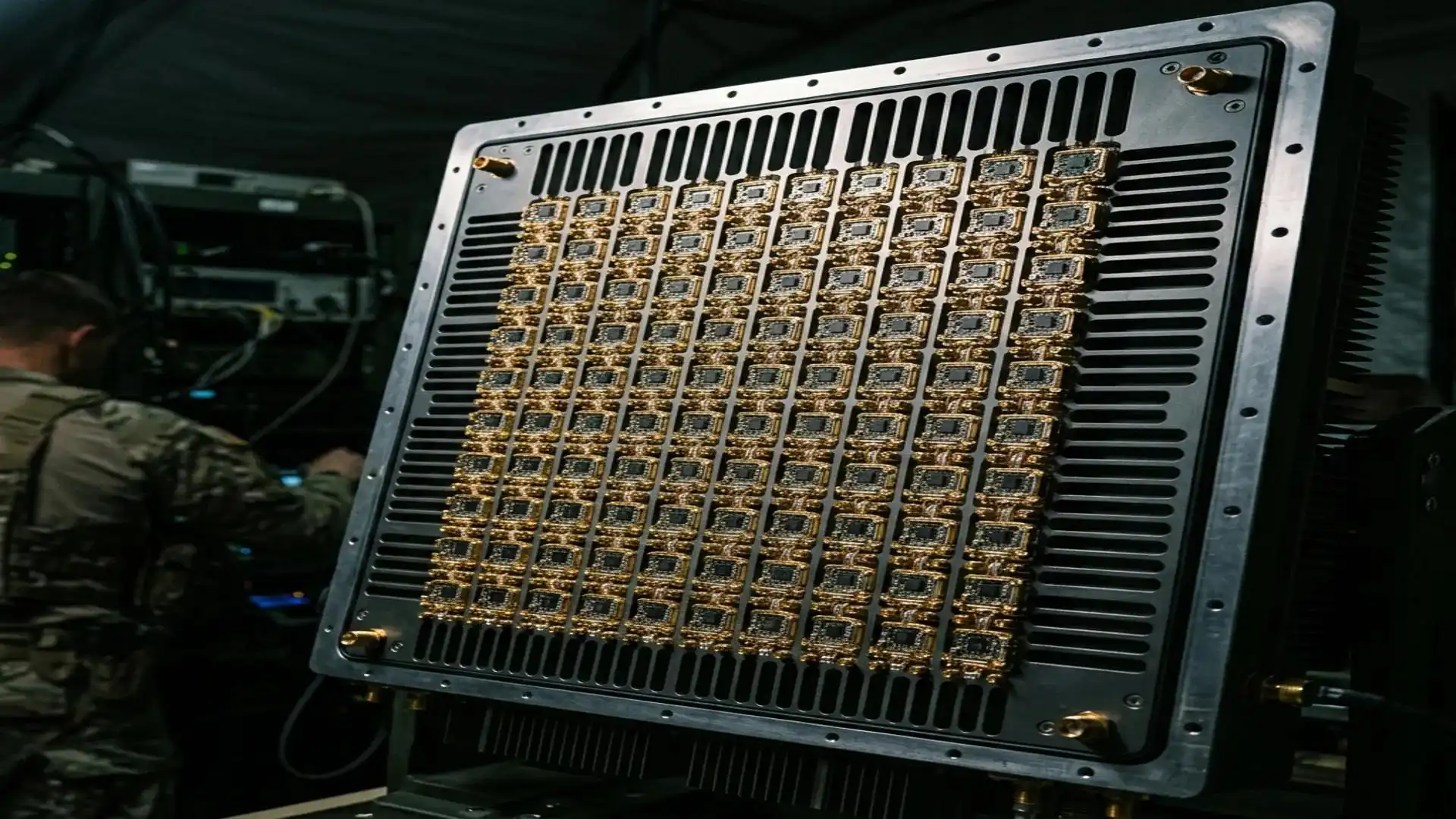
Signal chains in 5G base station backplanes can connect up to 10 or more connection ports. At 28 GHz, even a small amount of extra loss of 0.1 dB per connection adds up to 1 dB across ten interfaces, which is enough to lower the link margin and need more send power. The SBMA female right-angle flange mount connector has a rated insertion loss of ≒0.08√F(GHz) dB, which works out to about 0.42 dB at 28 GHz and is low enough to keep link budgets in dense arrays. When designing interconnects for phased-array antennas, makers of radar T/R modules use the same math.
Avoiding Common Installation Errors
Most of the time, high contact resistance after fitting is caused by poor blind-mate alignment during chassis assembly. The connector's float error allows for small changes in position, but contact surfaces are damaged when movement goes beyond the design limits. When engineering teams put together frames, fixture-guided processes help keep positional errors within the connector's stated float range.
Procurement Insights: Selecting and Purchasing Low Insertion Loss SBMA Female Right-Angle Flange Mount Connectors
There are both original manufacturers and secondary suppliers in the SBMA connector market. A structured review method is needed for procurement engineers who are in charge of $300,000 to $1,000,000 yearly budgets for RF components.
Evaluating Technical Data Sheets
An SBM data sheet that you can trustInsertion loss for a female right angle flange mount connection should be given as a frequency-dependent formula, not as a single flat number. Flat insertion loss claims from DC to 28 GHz don't make sense physically and point to a data source that can't be trusted. SIPU's specification of ≤0.08√F(GHz) dB is in the right frequency-dependent format and is in line with how measurements are done in IEEE 287.
Supplier Qualification for OEM Procurement
Batch uniformity and quality records that can be tracked are the most important things for communication system OEM engineers who are running sample-comparison approval processes. SIPU is certified by ISO 9001, and XRF analysis is used to check the quality of each batch of plating. Contact resistance measurements of ≤8.0 mΩ in the center and ≤3.0 mΩ on the edges are confirmed on every production batch. This gives procurement engineers proof that the quality of each delivery is the same.
Lead Time and Sample Support
Standard versions of the SIPU-SBMA-KWFB2G-1 are ready to ship in 72 hours from the factory in Xi'an. This response time lets engineers in the inquiry-to-sample-to-small-batch qualification flow make decisions in 3–6 months without putting the plan at risk. Custom mechanical setups get priority when it comes to setting production.
Future Trends Shaping SBMA Connector Performance
The RF connector industry is responding to frequency bands that continue to push higher and chassis geometries that continue to compress.
Miniaturization and Higher Frequency Demands
5G standalone deployments and emerging satellite communication bands are pushing interconnect requirements beyond 28 GHz toward 40 GHz and above. The material and geometry principles that make the current SBMA female right-angle flange mount connector perform well at 28 GHz — BeCu contacts, PTFE dielectric, precision-machined impedance transitions — are the same principles being applied to next-generation designs at higher frequencies.
Material Science Advances
Gold plating thickness optimization is an active area of supplier development. Thicker plating improves corrosion resistance and contact life, while excessive thickness can affect dimensional tolerances at submillimeter scales. Suppliers with in-house plating control and XRF verification are better positioned to maintain the balance between electrical performance and mechanical precision.
Supply Chain Stability for Long-Cycle Programs
Radar and defense OEM programs with 6–12 month qualification timelines require suppliers who can guarantee material consistency across multi-year production runs. SIPU's Xi'an manufacturing base, combined with its U.S. partner JNP Supplies LLC in Seattle, Washington, provides procurement teams with both production depth and regional supply chain support.
Conclusion
When it comes to high-density RF applications, the SBMA female right-angle flange mount connector stands out because it has low insertion loss. BeCu gold-plated contacts, PTFE dielectric, precise right-angle geometry, and rigid flange mounting work together to make sure that the electrical performance is good from DC to 28 GHz. This connector solves the main technical problems of signal integrity, space efficiency, and ease of placement for companies that make communication systems, radars, and test equipment. Batch-level quality control and standard delivery within 72 hours at SIPU help buying processes from the first sample all the way through to volume supply.
FAQ
1. What is the typical insertion loss for an SBMA connector at 28 GHz?
The SIPU-SBMA-KWFB2G-1 specifies insertion loss as ≤0.08√F(GHz) dB. At 28 GHz, this calculates to approximately 0.42 dB — a performance level suited for high-density backplane and radar applications.
2. Is the SBMA female right-angle flange mount connector interchangeable with SMP?
Both SBMA and SMP use slide-on blind-mate interfaces within the same connector family, making them functionally similar in concept. However, they are not dimensionally interchangeable. Always verify interface dimensions against your mating connector specification before ordering samples.
3. How does low insertion loss affect system maintenance costs?
Lower insertion loss reduces the transmit power required to maintain link margins. This decreases thermal load on power amplifiers, which extends component service intervals and reduces field replacement frequency in deployed systems.
4. What cable types work with this connector?
The SIPU-SBMA-KWFB2G-1 is compatible with RG405 and cables of equivalent specification. Engineers specifying alternate cable types should confirm outer diameter and dielectric dimensions against the connector's crimp termination geometry.
5. Does SIPU support custom configurations?
Yes. SIPU offers ODM and OEM customization covering mechanical design, frequency range, and plating specifications. Custom orders receive dedicated production line scheduling with priority logistics support.
Partner with SIPU for Your SBMA Female Right-Angle Flange Mount Connector Requirements
SIPU RF Technology has been making high-precision RF interconnects for more than 25 years. Their factories are ISO 9001 certified, and they usually deliver them within 72 hours. If you need samples to make sure the SBMA female right-angle flange mount connector works for you, small orders, or a lot of them, our team can help you with technical issues and offer good prices. To get a quote from a reliable SBMA female right-angle flange mount connector supplier, email us at info@sipu-rf.com or go to sipuconn.com.
References
1. IEEE Standard 287: Precision Coaxial Connectors (DC to 110 GHz) — IEEE, 2007
2. Microwave Engineering, David M. Pozar — Wiley, 4th Edition, 2011
3. RF and Microwave Engineering: Fundamentals of Wireless Communications, Frank Gustrau — Wiley, 2012
4. MIL-PRF-39012: Connectors, Coaxial, Radio Frequency, General Specification — U.S. Department of Defense, 2016
5. Passive RF and Microwave Components, Peter Vizmuller — Artech House, 1994
6. IEEE Transactions on Microwave Theory and Techniques: Contact Resistance and Insertion Loss in RF Connectors — IEEE, Vol. 58, 2010
Contact us directly for customized solutions, quotations and long-term strategic cooperation.