- English
- French
- German
- Portuguese
- Spanish
- Russian
- Japanese
- Korean
- Arabic
- Greek
- German
- Turkish
- Italian
- Danish
- Romanian
- Indonesian
- Czech
- Afrikaans
- Swedish
- Polish
- Basque
- Catalan
- Esperanto
- Hindi
- Lao
- Albanian
- Amharic
- Armenian
- Azerbaijani
- Belarusian
- Bengali
- Bosnian
- Bulgarian
- Cebuano
- Chichewa
- Corsican
- Croatian
- Dutch
- Estonian
- Filipino
- Finnish
- Frisian
- Galician
- Georgian
- Gujarati
- Haitian
- Hausa
- Hawaiian
- Hebrew
- Hmong
- Hungarian
- Icelandic
- Igbo
- Javanese
- Kannada
- Kazakh
- Khmer
- Kurdish
- Kyrgyz
- Latin
- Latvian
- Lithuanian
- Luxembou..
- Macedonian
- Malagasy
- Malay
- Malayalam
- Maltese
- Maori
- Marathi
- Mongolian
- Burmese
- Nepali
- Norwegian
- Pashto
- Persian
- Punjabi
- Serbian
- Sesotho
- Sinhala
- Slovak
- Slovenian
- Somali
- Samoan
- Scots Gaelic
- Shona
- Sindhi
- Sundanese
- Swahili
- Tajik
- Tamil
- Telugu
- Thai
- Ukrainian
- Urdu
- Uzbek
- Vietnamese
- Welsh
- Xhosa
- Yiddish
- Yoruba
- Zulu
Can an SMA Female Right Angle Connector Withstand Vibration?
A well-engineered SMA female right angle connector absolutely can withstand vibration. The threaded coupling interface locks the mating pair securely, preventing loosening under repetitive mechanical stress. Gold-plated beryllium bronze contacts and a PTFE dielectric maintain stable electrical contact even when the assembly experiences continuous shock or oscillation. In 5G base stations, aerospace enclosures, and industrial gateways, this connector type has demonstrated consistent RF performance across demanding field conditions. The key is selecting a connector built to the right mechanical and material specifications — which is exactly what this guide covers.
Understanding SMA Female Right Angle Connectors and Vibration Challenges
What This Connector Is Designed to Do
An SMA female right angle connector is a precise RF link that looks like an elbow and lets you connect cables with threads. When the characteristic impedance is kept at 50Ω, coaxial signals can be sent through containers that aren't very big. There were times when a straight link would either go too far into the frame or make the wire turn too much. The 90-degree turn keeps the solder joint and the insulator from being stressed by force.
Why Vibration Is a Real Engineering Concern
Connectors are always being shaken by things like cooling fans, compressors, moving vehicles, and wind loads in communications infrastructure, aerospace platforms, and industrial automation. IEC 60512-6 says that connection mating surfaces must keep the electricity flowing after certain sets of vibrations, which are usually sweep cycles at 10 to 200 Hz. There is more VSWR and insertion loss when a connection moves even a little. The signal quality also gets worse. For engineers in charge of 5G BBU or AAU RF lines, even small changes in VSWR can make the safety of the phase-locked loop less stable.
How the Right-Angle Geometry Helps
While the 90-degree shape makes it easier for a wire to grip the body of the connection, it also makes it less strong. The side force is stronger when the PCB footprint shakes and the cable run is long and straight. The force vector moves along the wire line instead of across the board when the design is at a right angle. This keeps the solder joints in good shape so they last longer.
Evaluating Vibration Resistance of SMA Female Right Angle Connectors
Material Composition Is the Foundation
The main thing that decides how well the link doesn't shake is what it's made of. Outer conductors made of gold-plated brass work well for most business and telecom needs because they are stiff enough and good at moving electricity. It's important that the low contact resistance stays the same even after thousands of shaking cycles, which is why beryllium bronze center contacts keep their spring force better. It doesn't change shape when it's between -65°C and +125°C, so the PTFE buffer doesn't change the resistance.
Threaded Coupling Locks the Interface
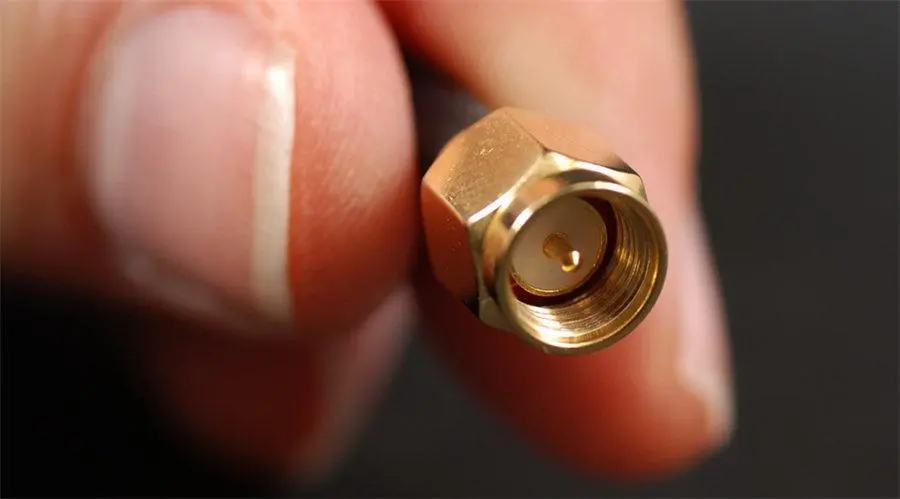
When you want to disconnect a SMA standard threaded connection, you have to do it on purpose, not like with push-on or snap-on RF interfaces. Because of this thread engagement, the SMA connector family works well in places where there is a lot of shaking. Putting on the suggested torque of 3–5 in-lbs for brass versions makes the threads create axial preload, which keeps them from coming loose when the machine shakes. Even though faster-mating choices are out there, this is one reason why SMA ports are still used in 5G small cells and BBU chassis designs.
Industry Standards Define the Baseline
At the very least, mechanical function must meet the standards of MIL-STD-348 and IEC 61169-15. In MIL-STD-202 Method 204, it says what kinds of vibrations connectors must be able to handle without losing power. Some of these factors are the range of frequencies, the amount of acceleration, and the length of time. Connectors that can pass these protocols have shown they can handle the stresses of being used in real life in systems on the ground and in the air.
Comparing SMA Right Angle Connectors with Alternative Solutions in Vibration-Prone Applications
SMA Right Angle vs. Straight SMA
If there is vibration, the wire can move straight into the mating contact with a straight SMA connection. You can see that the right-angle version messes up that load path. For tight PCB setups in 5G AAU boards or spectrum analyzer cases, the 90-degree shape makes the point where the board is attached less stressed. This means the board will last longer and still work properly electrically.
SMA vs. SMB and MCX in Vibration
An SMB and an mcx connector both use a snap-on connection. It's easier to put together quickly, but it's not as stable when the wire moves. Snap connections can come away when there is steady acceleration. Keep the signal going is very important for safety in places like military radar or electronics, so the threaded SMA interface is the safer and more common choice.
SMA vs. N-Type for Outdoor and High-Power Use
The N-type plug has a larger threaded interface, can handle more power, and can be sealed better for use outside. When you need to route radio waves at the board level inside equipment cases, like in 5G base stations, the small SMA right angle connector is better. To connect feeders and antennas, N-type connections are most often used. They are not used for wiring inside the frame.
Procurement Guide: Selecting Vibration-Resistant SMA Female Right Angle Connectors
Specifications to Prioritize
When sourcing a vibration-resistant SMA female right angle connector, the following specifications deserve careful review. These parameters directly affect mechanical and electrical performance in field conditions:
- VSWR: Look for ≤1.06+0.015F(GHz) across DC–12.4GHz. Higher VSWR under vibration indicates interface degradation.
- Contact resistance: Center contact ≤3.0mΩ and outer contact ≤2.0mΩ ensure minimal signal loss under mechanical stress.
- Mating cycles: 500 cycles minimum supports long service life in frequently accessed chassis.
- Operating temperature: -65°C to +125°C covers both outdoor telecom and avionics thermal ranges.
- Cable compatibility: Verify compatibility with your cable type (e.g., CXN3506) to avoid impedance discontinuities at the cable-connector junction.
Reviewing these figures across supplier datasheets gives procurement engineers an objective basis for comparison rather than relying on marketing claims alone.
Supplier Qualification Criteria
Not just product specification sheets should be asked for, but also batch test results. For each production lot, a reliable supplier will give you information on the plating thickness, records of the measurements that were taken, and the electrical results that were checked. If you want to buy a lot of something, ask the manufacturer if they have dedicated production lines with ISO 9001 process controls. Check that the product meets the requirements of RoHS, REACH, IEC, and CE. This is especially important for goods that will be sold in the US and Europe.
Sample Testing Before Volume Commitment
Before committing to a production order, request engineering samples and run your own VSWR and insertion loss measurements using a VNA. Subject samples to your application's vibration profile — even a basic sinusoidal sweep at 10–500 Hz will reveal whether the mating interface loosens or the electrical parameters drift. This step is standard practice for 5G OEM procurement teams and is expected by serious suppliers.
Installation Best Practices to Improve Vibration Resistance
Apply Correct Torque
Links that aren't tight enough come loose when there are shocks, and links that are too tight damage the threads and bend the dielectric. Brass SMA connectors should be three to five inches-pounds. When you need to fix something by hand, use a torque wrench that has been gaged. This is very important for parts that you won't be able to reach again after the job is done.
Provide Cable Support Near the Connector
At the place where the cable comes out, there is strain relief. So, the weight of the cable and its ability to bend don't put stress on the connection bodies. Inside 50 mm of the join, you should use cable ties, saddle clamps, or route guides to keep the wire in place. This easy step makes the solder joint and the place where the two parts fit together much less likely to get damaged.
Conduct Periodic Mechanical Inspections
Connectors that have been installed correctly can still benefit from being looked at every so often. When you look at the places where the two parts fit together, make sure there are no gaps, thread galling, or worn gold coating. In a built system, the hardest type of RF failure to figure out is the kind that happens over and over again because of slow VSWR rise. Finding wear early stops this kind of failure.
Conclusion
RF connectors don't have vibration resistance by accident; it's because of the materials used, the careful design of the mechanics, and the consistent production. It has a threaded SMA interface, a beryllium metal contact, and a PTFE dielectric. The SMA female right angle connector is round. It is strong enough to work consistently in 5G base stations, aircraft enclosures, industrial ports, and test tools because of this. If you want to avoid field failures caused by connection degradation due to vibration, pick a connector that meets the requirements set by IEC 61169-15 and MIL-STD-348. Also, test a sample to make sure it works before ordering a lot of them.
Frequently Asked Questions
1. What vibration levels can an SMA female right angle connector typically tolerate?
Connectors compliant with MIL-STD-202 Method 204 are tested at acceleration levels up to 15G across 10–2,000 Hz. Most commercial-grade SMA connectors handle lower profiles. Always verify the specific vibration test data in the supplier's qualification report before specifying for high-vibration applications.
2. Are these connectors suitable for outdoor mobile environments?
Yes, provided the operating temperature range (-65°C to +125°C) and material corrosion resistance meet your environment's demands. For direct moisture exposure, add a protective enclosure or specify IP-rated cable assemblies around the connector body.
3. What are early signs of vibration-induced connector damage?
Watch for rising VSWR during periodic RF checks, intermittent signal dropouts, or visible thread wear on the coupling nut. Any contact resistance reading above the specified maximum is also a reliable indicator of mechanical degradation.
4. Does the right-angle geometry weaken the connector mechanically?
No. The 90-degree elbow actually reduces lateral cable leverage at the PCB attachment point. Precision machining of the bend maintains impedance continuity, with VSWR typically within specification up to the connector's rated frequency ceiling.
5. How many mating cycles should I expect before replacement?
SIPU's SIPU-SMA-KW3506 is rated for 500 mating cycles. For test bench applications with frequent connect/disconnect, track cumulative cycles and replace connectors before the rated limit to avoid performance drift.
Get Vibration-Tested SMA Female Right Angle Connectors from SIPU
SIPU RF Technology has been making high-precision RF connection hardware since 1998. A VSWR of ≤1.06+0.015F(GHz) is found in the SIPU-SMA-KW3506 SMA female right angle connector, which can be stacked 500 times. RoHS, REACH, IEC, and CE all say that it is safe. You can get what you need from SIPU on time, whether you need engineering samples to test a prototype or a lot of them with lots of detailed batch testing. Email our team at info@sipu-rf.com or visit sipuconn.com to get a copy or sample for your next project.
References
1. IEC 60512-6-4: Connectors for Electronic Equipment — Tests and Measurements — Part 6-4: Dynamic Stress Tests — Vibration (Sinusoidal). International Electrotechnical Commission, 2007.
2. MIL-STD-202H: Test Method Standard for Electronic and Electrical Component Parts. U.S. Department of Defense, 2015.
3. MIL-STD-348B: Interface Standard for RF Connector Interfaces for MIL-DTL-39012 Connectors. U.S. Department of Defense, 2011.
4. IEC 61169-15: Radio-Frequency Connectors — Part 15: Sectional Specification for rf coaxial connectors of Series SMA. International Electrotechnical Commission, 2013.
5. Laverghetta, T.S.: Handbook of Microwave Testing. Artech House, 1981. (Reprinted and cited in connector mechanical performance literature through 2019.)
6. Montrose, M.I.: EMC and the Printed Circuit Board: Design, Theory, and Layout Made Simple. IEEE Press / Wiley, 1999.
Contact us directly for customized solutions, quotations and long-term strategic cooperation.