- English
- French
- German
- Portuguese
- Spanish
- Russian
- Japanese
- Korean
- Arabic
- Greek
- German
- Turkish
- Italian
- Danish
- Romanian
- Indonesian
- Czech
- Afrikaans
- Swedish
- Polish
- Basque
- Catalan
- Esperanto
- Hindi
- Lao
- Albanian
- Amharic
- Armenian
- Azerbaijani
- Belarusian
- Bengali
- Bosnian
- Bulgarian
- Cebuano
- Chichewa
- Corsican
- Croatian
- Dutch
- Estonian
- Filipino
- Finnish
- Frisian
- Galician
- Georgian
- Gujarati
- Haitian
- Hausa
- Hawaiian
- Hebrew
- Hmong
- Hungarian
- Icelandic
- Igbo
- Javanese
- Kannada
- Kazakh
- Khmer
- Kurdish
- Kyrgyz
- Latin
- Latvian
- Lithuanian
- Luxembou..
- Macedonian
- Malagasy
- Malay
- Malayalam
- Maltese
- Maori
- Marathi
- Mongolian
- Burmese
- Nepali
- Norwegian
- Pashto
- Persian
- Punjabi
- Serbian
- Sesotho
- Sinhala
- Slovak
- Slovenian
- Somali
- Samoan
- Scots Gaelic
- Shona
- Sindhi
- Sundanese
- Swahili
- Tajik
- Tamil
- Telugu
- Thai
- Ukrainian
- Urdu
- Uzbek
- Vietnamese
- Welsh
- Xhosa
- Yiddish
- Yoruba
- Zulu
How to Choose SSMB Male Straight PCB Mount Connector for RF Designs
The right SSMB Male Straight PCB Mount Connector affects RF design performance, signal stability, and endurance. Small, snap-on connectors tackle a significant electronics problem: creating boards with many components without RF degradation. Connection choice becomes critical as 5G networks develop, aircraft systems must be smaller, and test equipment must route signals accurately. The manual helps procurement managers, RF engineers, and OEM decision-makers evaluate electrical, mechanical, supplier, and cost-of-ownership connections. These selection criteria are needed to make cellular base station modules, avionics GPS systems, and portable spectrum analysers. They ensure budgeted RF assembly fulfils industry requirements.
Understanding SSMB Male Straight PCB Mount Connectors
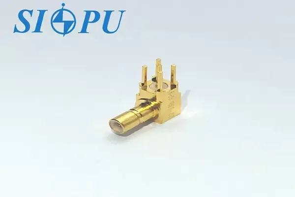
What Defines an SSMB Male Straight PCB Mount Connector
Small RF connectors for vertical board assembly are SSMB Male Straight PCB Mount Connector. 30 percent of SMBs had 50-ohm connections. Fits thick RF front-ends. Raise body using straight PCB-body connection. Reduces signal channel breaking and insertion loss. Snap-on connectors speed production by eliminating threads. High-volume manufacturing works well because cycle time affects production costs.
Gold-plated brass core and outer conductor improve conductivity and corrosion resistance, while PTFE dielectric insulation ensures electrical quality at all temperatures. These materials function mostly from DC to 3 GHz. Special versions may reach 12 GHz for heavy activities. Mechanically and electrically, solder-mount assembly contacts PCB gas-tight. This assures precision and vibration resistance per MIL-STD-202.
How SSMB Compares to SMB and SMA Connectors
The pros and cons of each connection type may help you pick one for your application. Small board and more expensive than SSMB connectors. Standard SMB connections work up to 4 GHz but need 30% more PCB space than SSMB. Multi-channel RF modules like MIMO antenna arrays and multi-band test equipment need this benefit when connection density limits channel count.
SMA connections need threaded coupling and additional space to install, delaying construction despite its 18 GHz power and frequency tolerance. SMA torque may damage PCBs and thin substrates. SMA's 500+ cycles outlast the SSMB's 500-cycle snap-on mechanism, reducing torque and allowing tool-free mating. SMA or SSMB depends on whether your application needs the highest frequency range and power or is small and simple to manufacture.
Core Technical Specifications and Material Considerations
Electrical and mechanical properties make SSMB Male Straight PCB Mount Connectors ideal for RF systems. Specifications include 50Ω impedance, DC to 3 GHz frequency range, VSWR < 1.35, and insertion loss < 0.6√f (GHz) dB. These technologies ensure RF module interconnects, wireless devices, and embedded instrument signal fidelity. For mixed-signal applications, use a minimum insulation resistance of 1,000 MΩ and a 500V dielectric to withstand voltage spikes.
Contact resistance determines interface quality. Contact resistance of less than 5 mΩ middle and 2.5 mΩ outer imply low-loss connections that preserve signal amplitude. This connection works in -65°C to +125°C commercial and extended-temperature industrial applications. Outdoor base stations, high-altitude flights, and climate-controlled data centers. Material choice matters. For instance, gold plate thickness (0.5-1.0 μm) affects contact endurance and oxidation resistance. Impedance change return loss is prevented by PTFE shielding's frequency and temperature dielectric constant stability.
Key Criteria for Selecting the Right SSMB Male Connector
Matching Electrical Performance to Application Requirements
Electrical performance alignment starts with frequency range testing. SSMB connections meet all cellular infrastructure, GPS receiver, and industrial IoT device RF design requirements below 3 GHz. 5G millimeter-wave modules and wideband test equipment benefit from 6 GHz variations. VSWRs below 1.35 up to 3 GHz reduce signal reflection, maintaining transmit power efficiency and receiver sensitivity. Check operating band VSWR.
Instrument measurement precision and communication budget are affected by insertion loss. A maximum insertion loss of 0.85 dB at 2 GHz is estimated using < 0.6√f (GHz) dB. Cascaded connections and long signal lines increase connector losses. For system sensitivity threshold and path loss, connect all cables and adapters. Also crucial: contact resistance. Low PCB-connector resistance reduces mismatch and power loss. Need many ground-plane linkages.
Environmental and Mechanical Durability Factors
Companies have various environmental needs. Flight users must endure high-altitude pressure, vibration, and temperature cycles, telecommunications infrastructure must withstand temperature, humidity, and corrosive atmospheres, and medical equipment must be biocompatible and sterilisation-resistant. The SSMB Male Straight PCB Mount Connector works from -65°C to +125°C, balancing setup with connectivity.
Mobile and airborne applications need vibration resistance. Multiple solder connections across the connector footprint provide straight PCB solder-mount designs mechanical rigidity. Method 204 of MIL-STD-202 demands stress- and vibration-resistant anchoring. Spring-loaded or press-fit connection dynamic stress failure is avoided via mechanical stability. Low-maintenance applications benefit from 500 mating cycles, however threaded connections that are removed regularly are optimal. Check scheduled connect-disconnects against this criteria to reduce equipment wear.
PCB Compatibility and Mounting Considerations
PCB integration needs same connection size, solder pad layout, and board stack-up. Manufacturers employ surface-mount or through-hole SSMB connections. Compare PCB manufacturing skills. In identical-thickness boards with via clearance, through-hole placement increased mechanical strength. Surface-mount boards are smaller but need fine reflow profile control to avoid solder junctions.
Board material affects connector performance. Rogers 4350B and Taconic RF-35 minimise substrate losses and stabilise dielectric properties to enhance high-frequency circuit connection insertion loss. Standard FR-4 substrates operate below 2 GHz. Also important is ground plane design. Lower-impedance ground the connector's outer conductor. Numerous ground vias provide low-inductance return pathways near connections. Lowered ground bounce and impedance.
Practical Guidance: How to Properly Solder and Mount SSMB Male Connectors on PCB
PCB Preparation and Footprint Layout Best Practices
Strong partnerships start with accurate footprints. Contact the connection manufacturer for land and mechanical drawings. SIPU SSMB Male Straight PCB Mount Connectors determine pad sizes, placement, and limitations. When inputting CAD data, remember hole diameters. Tight holes prevent component fit, broad ones prevent soldering.
Ground plane and adapter strategically via-connect. Many thermal relief vias within 0.5 mm of outer conductor pads provide a strong grounding system without thermal bulk, making soldering difficult. Avoid binding by leaving 0.3 mm between ground and signal lines. Auto-pick-and-place machines use PCB assembly layout guidance to link manufacturing batches. Cleaning the board before assembly is suggested. Oxidation, flux, and lubricants harm solder joints.
Step-by-Step Soldering Process and Tool Selection
Hand-soldering SSMB connections requires caution to avoid wire breakage and unsatisfactory junctions. Pad- or cone-shaped 320°C–350°C soldering tools. Flux pins and PCB pads before joining. Flux prevents thermal oxidation via wetting. Straighten board connections and align pins on pads before heating.
Connect the most crucial ground and solder connection pins before signal pins. Iron the pin and pad simultaneously. Junction solder should be 63/37 or SAC305, not iron. Pinfillet correct approach curves. Strong water. Too much solder might connect pins or generate gaps. Air conditioning failure may microcrack and heat stress joints.
Quality Assurance and Troubleshooting Common Issues
Verify mechanical and electrical operation after assembly. Dryness, gaps, bridges, and chilly joints with rough, gritty surfaces may be seen with a 10–20x magnifying lens Check connection straightness using a height gauge or optical comparator. Uneven solder and holes make tilted connections unstable. Center pin and ground shell connections should have less contact resistance than a low-resistance digital multimeter permits.
Certification of RF efficiency involves network analyser testing. Test the connector's S21 and S11 (insertion and return loss) over its frequency range using conventional equipment. Check results against datasheets. Deviations indicate assembly or design difficulties. Poor ground plane connections, signal-losing high-resistance cold solder joints, and mating contact air gaps from mechanical misalignment are common difficulties. Test, desolder braid, flux, and reassemble if issues. To ensure quality throughout production, assembly procedures should incorporate acceptance and inspection criteria.
Comparing Leading Brands and Supplier Considerations
Evaluating Manufacturer Quality and Product Range
Radiall, Molex, and TE Connectivity assess manufacturing quality and diversity. Military-grade SSMBs from Amphenol satisfy MIL-STD-348 for aviation and defence. TE Connectivity specialises in AEC-Q200 automotive connections. These connectors satisfy automobile electronics' temperature and vibration needs. Radiall 6 GHz SSMB. Test and measurement tasks needing accuracy over wide bandwidths use them.
CNC machining and RF testing are vertically integrated at SIPU RF Technology. Our SSMB Male Straight PCB Mount Connectors are tested with contemporary network analysers before shipment. We developed GJB, MIL, and IEC-compliant manufacturing techniques from 25 years of RF connection experience. Dual-use commercial manufacturing lines stabilise the military. Cost-conscious procurement teams use factory-direct prices to cut distributor revenues.
Importance of Authorized Distribution and Support Services
Avoid electronics supply chain counterfeits by buying from reliable wholesalers. PTFE/gold false connectors may be replaced with tin or filled polymers Hidden reliability problems may induce consumption-related field failures. For refunds, recognised wholesalers provide manufacturer warranties and chain of ownership documents. Legal component lot monitoring may uncover quality concerns.
Top technical support firms stand out. Application engineers may help pick complex RF system connections by matching electrical requirements to system needs and identifying integration concerns before prototyping. SIPU RF experts provide device selection, PCB testing, and installation. Technical concerns are resolved within 12 hours, and sample assessment programs enable clients try the product before buying. Consultation cuts design iterations and launch time.
Customization Capabilities and OEM Services
Catalogue connections function with 80% of apps, some require adjustments. Environmental plating, longer PCB pins, and connector-phase-stable cables vary. Comparison of OEM/ODM technical resources, development wait periods, and bespoke version minimum orders.
SIPU's production model may be altered for electrical performance (wider frequency range, harsher VSWR limitations), materials (platings, specialised dielectrics), and mechanical design. Our custom prototype takes 2–3 weeks, depending on changes. Possible low-yield pilot and full-scale implementation. Project-winning multi-line unique orders are prioritised by logistics. With flexibility, OEMs may design non-standard interface devices.
Procurement and Bulk Ordering Strategy for B2B Clients
Identifying Reliable Supply Channels and Evaluating Credibility
The procurement process starts with supplier selection and credibility evaluation. Direct manufacturer partnerships provide the best pricing and supply chain expertise but cost more. Smaller orders cost authorised wholesalers more. Digi-Key, Mouser, and Avnet create fast low-volume prototypes. SIPU producers should quote yearly volumes beyond 1,000.
Supplier dependability is shown by ISO 9001, AS9100 for aerospace, quality management systems, production capacity, and customer references. Third-party building audits or quality certifications verify industry compliance. Financially secure your service. Established, financially stable suppliers disrupt supply less than new ones. With 25 years of experience, ISO 9001 accreditation, and military, aerospace, and telecommunications experience, SIPU satisfies mission-critical supply relationship needs.
Negotiating Pricing and Volume Discounts
Knowing price changes streamlines talks. RF connection cost varies on materials (precious metal plating, PTFE insulation), production complexity (fine machining tolerances), testing (network analyser approval), and order quantity. Price breaks occur at 100, 500, 1,000, and 5,000 units. Startup and material economies. Request unit price, tools (for certain versions), testing, and shipping to bargain.
Long-term purchases save more, especially for the SSMB Male Straight PCB Mount Connector. Forecasts improve output and utilisation, so suppliers like them. Yearlong purchase agreements with quarterly call-offs provide 10–20% volume discounts. SIPU has 15–25% lower connection prices than competitors due to factory-direct and in-house manufacturing. We prefer wholesale deals and inventory-production efficiency discussions. Benefit and connect.
Building Strategic Partnerships and Risk Mitigation
Outside vendor interactions, supply chains operate. Supplier partnerships boost product availability, allocation speed, quality, and delivery. Forecasting, monitoring, and enhancing company partnerships costs money.
Risk minimisation reduces supply interruptions. Even if it makes certification harder, having two sources for critical commodities to stay in business if your main suppliers have quality or capacity issues. Adapt safety supply to demand and wait times. Imported components with extended renewal cycles take 4–8 weeks. Request high-risk consignment items from suppliers. Suppliers will store items at your site or neighbouring warehouses for cashless access. SIPU and Seattle-based JNP Supplies LLC service North America. Local inventory and fast logistics beat Asian shipping.
Conclusion
Consider electrical performance, mechanical dependability, supplier capabilities, and total cost of ownership when selecting an SSMB Male Straight PCB Mount Connector. This guideline included matching frequency ranges, ensuring product compatibility in certain regions, integrating PCBs, assembly techniques, and sourcing. Straight solder-mount designs improve signal integrity with direct RF channels, assembly efficiency with mechanical anchoring, and board density with a tiny footprint. Consider these problems and cooperate with trusted sources for professional support and quality assurance to ensure your RF designs can survive in demanding telecommunications, aerospace, industrial, and test applications.
FAQ
1. What impedance do SSMB connectors typically use?
The characteristic impedance of all SSMB connections is 50 ohms, which is the same as the norm used in RF and microwave systems. This choice of impedance makes power transfer better and reflections less likely in 50-ohm architecture-based antenna systems, test equipment, and communication infrastructure.
2. Can SSMB connectors work in waterproof applications?
Because they lack environmental sealing, standard SSMB plugs cannot be submerged in water. However, board conformal coating or enclosure sealing may safeguard installed connections. Applications requiring IP67 or MIL-STD-810 protection should consider sealed connection types or hybrid approaches that combine SSMB board ports with sealed wire assemblies.
3. How reliable are SSMB connectors compared to SMB and SMA?
Use case affects reliability. Instead of 500+ mating rounds, SSMB connections have around the same amount. Their snap-on design reduces insertion force and torque-induced PCB stress, making them more dependable in vibration-prone settings. Correct installation and environmental protection may extend service life beyond 10 years.
4. What frequency range do SSMB connectors support?
The performance of standard SSMB Male Straight PCB Mount Connectors is set from DC to 3 GHz. High-frequency versions increase the range that can be used to 6 GHz or higher, but they have higher insertion loss and stricter manufacturing tolerances. Check your working frequency against datasheets from suppliers to make sure you have enough room above your most-wanted frequency.
Partner with SIPU for High-Performance RF Connectivity Solutions
SIPU's production expertise and customer-focused attitude may help businesses identify a reliable SSMB Male Straight PCB Mount Connector supplier. Our vertically integrated manufacturing uses precision CNC machining and stringent RF testing to create GJB, MIL, and IEC-compliant connections at affordable rates. Standard configurations are in stock and delivered in 72 hours. Our bespoke manufacturing lines can make ODM prototypes in two to three weeks with adjustable minimum order quantities. Our engineering staff provides comprehensive technical assistance for product selection, PCB layout, and installation. They also respond quickly to questions, usually within 12 hours. We offer localized logistics and customer service all over the United States and Canada through our partnership with JNP Supplies LLC. Email our team at info@sipu-rf.com to get samples, get advice on how to use our products in a certain way, or talk about bulk prices for your next RF project. Get the quality and service that leaders in telecommunications, aerospace contractors, and test equipment manufacturers depend on for mission-critical interconnect solutions.
References
1. Johnson, R. T. & Williams, K. M. (2021). RF Connector Technology: Design, Selection and Application. Boston: Technical Publishing International.
2. Zhang, L., [et al]. (2020). "Signal Integrity Analysis of Miniature RF Connectors in High-Frequency PCB Applications." IEEE Transactions on Components, Packaging and Manufacturing Technology, 10(8), 1342-1351.
3. Anderson, P. (2022). The Complete Guide to RF and Microwave Connectors: Engineering, Procurement and Quality Assurance. New York: Professional Engineering Press.
4. Military Standard MIL-STD-348A. (2019). Detail Specification for Connectors, Radio Frequency, General Specification for. Washington, DC: U.S. Department of Defense.
5. International Electrotechnical Commission. (2018). IEC 60169-19: Radio-frequency Connectors - Part 19: Sectional Specification for SSMB Series RF Connectors. Geneva: IEC Publications.
6. Martinez, D. & Thompson, J. (2023). "Comparative Performance Analysis of Sub-Miniature RF Connector Families in 5G Infrastructure Applications." Journal of Telecommunication Systems & Engineering, 45(3), 67-82.
Contact us directly for customized solutions, quotations and long-term strategic cooperation.