- English
- French
- German
- Portuguese
- Spanish
- Russian
- Japanese
- Korean
- Arabic
- Greek
- German
- Turkish
- Italian
- Danish
- Romanian
- Indonesian
- Czech
- Afrikaans
- Swedish
- Polish
- Basque
- Catalan
- Esperanto
- Hindi
- Lao
- Albanian
- Amharic
- Armenian
- Azerbaijani
- Belarusian
- Bengali
- Bosnian
- Bulgarian
- Cebuano
- Chichewa
- Corsican
- Croatian
- Dutch
- Estonian
- Filipino
- Finnish
- Frisian
- Galician
- Georgian
- Gujarati
- Haitian
- Hausa
- Hawaiian
- Hebrew
- Hmong
- Hungarian
- Icelandic
- Igbo
- Javanese
- Kannada
- Kazakh
- Khmer
- Kurdish
- Kyrgyz
- Latin
- Latvian
- Lithuanian
- Luxembou..
- Macedonian
- Malagasy
- Malay
- Malayalam
- Maltese
- Maori
- Marathi
- Mongolian
- Burmese
- Nepali
- Norwegian
- Pashto
- Persian
- Punjabi
- Serbian
- Sesotho
- Sinhala
- Slovak
- Slovenian
- Somali
- Samoan
- Scots Gaelic
- Shona
- Sindhi
- Sundanese
- Swahili
- Tajik
- Tamil
- Telugu
- Thai
- Ukrainian
- Urdu
- Uzbek
- Vietnamese
- Welsh
- Xhosa
- Yiddish
- Yoruba
- Zulu
How to Select SSMB Male Straight PCB Mount Connector Step by Step
Balance pricing, mechanical reliability, and electrical performance to choose the best SSMB Male Straight PCB Mount Connector. High-density PCBs with limited space and high signal integrity benefit from this 50-ohm connection. The best choice depends on frequency range (DC–3 GHz), VSWR, mounting compatibility, and supplier capabilities. To integrate telecommunications infrastructure, aviation avionics, test equipment, and industrial electronics, engineers and procurement managers must match technological goals with production timelines and budgets. Find connections that meet strict operating criteria with this advice.
Understanding SSMB Male Straight PCB Mount Connectors
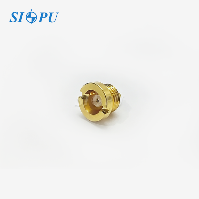
Modern electronics use SSMB Male Straight PCB Mount Connectors to unblock interconnects. Compact 50-ohm SMB connectors use a third less board space. Return and insertion loss breaks are eliminated in straight vertical paths, giving a direct signal channel.
Core Features and Applications
Links are useful in many ways. High-density vertical telecommunications uses micro cells and base station modules. Military and aerospace flight control computers and GPS navigation modules employ snap-on connection and MIL-STD-202 vibration compliance. Several portable spectrum analysers and medical diagnostic tools utilise them to connect and disengage without signal loss. At high temperatures, PTFE dielectric insulation maintains electrical characteristics. Gold-plated bronze contacts have low contact resistance (central < 5.0 mΩ, external ≤ 2.5 mΩ). By removing torque wrenches, solder-mount systems speed up automated assembly and lower mass-produced plant labour costs.
Key Specifications Impact on System Performance
Connection width depends on frequency. Standard versions utilise DC up to 3 GHz; wideband uses 12 GHz. VSWR limit (< 1.35 at 3 GHz) enhances impedance matching, impacting reflected power and system performance. The interface signal loss is assessed via insertion loss (≤ 0.6 GHz dB). Size impacts PCB density. Close arrays without RF isolation are possible due to their modest size. Mating cycle rates (≥ 500 cycles) indicate relationship viability with proper management. The working temperature (-65°C to +125°C) allows it to withstand harsh outdoor communication and aviation systems.
Comparative Analysis: SSMB vs. SMB, SMA, and MCX
Connection families help choose app parts. SMB connections are straightforward to plug but take up PCB space, making them unsuitable for tiny designs. Threaded SMA connections are faster (up to 18 GHz) but need hand-torqueing, assembly delays, and costly labour. Smaller than SSMB, MCX connectors lock push-pull. Tool-free mating and little board space make SSMB Male Straight PCB Mount Connectors ideal for DC to 3 GHz applications. Every PCB millimetre costs money and reduces RF front-end congestion most.
Step 1 – Define Your Technical Requirements
Standardisation reduces redesign and supply chain delays. For electrical, mechanical, and environmental compliance, engineers must relate system-level performance objectives to connection requirements.
Assessing Frequency Range and Electrical Performance
Bandwidth without power loss relies on connection frequency. GSM/LTE base stations, Wi-Fi modules, and industrial IoT sensors below 3 GHz benefit from SSMB Male Straight PCB Mount Connectors (insertion loss < 0.6√f (GHz) dB). Above 3 GHz, wideband radar or millimeter-wave test equipment may demand tighter tolerances. Controlling transmission line impedance protects signals. In many RF systems, a 50-ohm characteristic resistance minimises standing waves and enhances power transmission. Equipment having VSWR < 1.35 reflects less than 4% power back to the source. Avoiding sensitive amplifier failure improves test equipment accuracy. Insulation resistance over 1,000 MΩ inhibits current leakage in receiver circuits.
Mechanical Considerations for PCB Integration
PCB installation impacts production and reliability. Fixed mechanical attachment and electrical contact reduce shaking and temperature-induced contact resistance fluctuations in solder-mount systems. Vertical perpendicular signals help PCB design. Reduces circuit crosstalk and trace length. Connector pin patterns must match PCB designs or allow new layouts for footprint compatibility. SSMB connections link tiny boards with high-density RF lines in phased array antennas and multi-channel data collecting systems. Straight or right-angle wiring. Right-angle connectors reduce parallel cable solder joint stress, although straight connections are best for perpendicular wires.
Environmental Durability and Operational Stress
Safe and effective temperature range. Arctic winter and desert summer communications equipment and aircraft platforms with frequent altitude changes may use -65°C to +125°C connections. Material choice affects thermal stability. Gold-plated connections don't oxidise, reducing contact resistance, while PTFE dielectrics have a low temperature loss slope. Auto and aerospace applications with frequent mechanical shocks need vibration resistance. The PCB solder-mount design spreads pull over several solder connections. With 500 mate cycle rates, connections may be repaired without electrical degradation. Daily test equipment calibration is needed.
Step 2 – Compare Connector Options and Brands
Tech and manufacturing decide links. Check VSWR, frequency, and insertion loss. Supplier quality and personalisation affect long-term partnerships.
Evaluation Criteria for Performance and Quality
Insertion loss is connectivity interface signal loss. Decibels. Low-signal communications system receivers and test equipment are more sensitive and accurate. Material quality impacts loss. Precision-machined brass bodies and gold-plated connectors reduce resistive losses and impedance variations. VSWR measures frequency-matched impedance. Design reduces reflections, digital bit error rates, and frequency response measurement ripples. Highest connectivity. Since parasitic inductances and capacitances affect circuit responsiveness, exceeding this limit may induce unexpected behaviour.
Leading Manufacturer Profiles and Capabilities
Global titans develop SSMB collaboration. Amphenol sells military and commercial hardware. They customise for MIL-DTL-39012-compliant military firms. TE Connectivity needs mass-production efficiency. Telecom OEMs benefit from automated testing and supply chain optimisation. Radial DO-160 links. Pasternack's quick prototyping lets test and measurement companies test concepts before buying manufacturing equipment. Molex produces compact medical imaging equipment using SSMB Male Straight PCB Mount Connector designs. Smiths links military/space, Huber+Suhner makes telecom.
SIPU RF Technology can pilot mass production after 28 years. CNC cutting and RF testing are GJB, MIL, and IEC-approved. B2B shipping is cheaper and faster with domestic manufacture.
Cost Considerations and Procurement Strategy
Order quantity, customisation intricacy, and materials affect wholesale cost. Tools and testing make custom-engineered goods more costly than catalogue items. Frequent purchasers save more. Most prices drop at 1,000, 5,000, and 10,000 pieces. Production and inventory affect lead times. OTS prototypes save 72 hours. Custom orders need two to six weeks for tooling, manufacture, and approval. Early supplier communication boosts assembly. Technical support, warranties, and supplies boost cost-effectiveness.
Step 3 – Procurement Best Practices for B2B Clients
Strategic buying extends beyond parts. Also included are supplier relationships, contract requirements, and supply chain risk management. Successful buyers assess, negotiate bulk discounts, and prepare for emergencies.
Strategic Sourcing Decisions
Authorised dealers provide manufacturer insurance and credibility. Reduces fake part failure early or inconsistently. Online platforms simplify browsing and modest purchases but may lack application-specific professional guidance. Manufacturer-customized orders cost more and take longer but increase performance and features. Fewer vendors provide bulk discounts. Deal better and keep quality. Long-term projects need pricing stability to avoid material price swings. On-time delivery, fault rates, and responsiveness demonstrate supplier dependability above cost.
Managing Lead Times and Logistics
Production schedules impact sales, especially for components like the SSMB Male Straight PCB Mount Connector. Just-in-time lowers inventory costs but increases supply chain risk. Buffer stock avoids delays but needs operational resources and may become outdated if project requirements alter. Manufacturer-supplier coordination maintains output and supply. Shipping affects landing cost and predictability. Air freight is speedier but more expensive for urgent goods. Ocean freight is cheap yet sluggish for huge volumes. SIPU's Seattle cooperation with JNP Supplies LLC may cut production schedule imports as local warehouses respond quicker.
Product Authenticity and Warranty Verification
Faults and power waste from improper connections impair system dependability. Valid package labels, manufacturer conformity certificates, and samples examined immediately after delivery are needed for verification. Authorised distributors track sources. Warranty avoids manufacturing defects and early failure. Damaged equipment may be replaced or reimbursed 12–24 months after delivery. Extended warranties protect mission-critical devices against expensive or dangerous field failures. Technical troubleshooting and application engineering cost more for complex projects.
Step 4 – Installation and Application Tips
Install properly to maintain connection performance and avoid early failures. PCB pad design, solder quality, and post-installation testing affect system dependability.
PCB Mounting and Soldering Best Practices
Prepare PCB pads before soldering. Pads must match pins and have enough copper to resist mechanical stress without straining solder. Reflow contamination, shorts, and weak connections are avoided via solder mask removal. Too much solder paste bridges, reducing mechanical connection. Wet all solder to improve reflow and prevent PTFE insulation heat damage. To avoid dielectric breakdown, lead-free solders should not exceed 260°C for 60–90 seconds. Cooling speed affects solder connection composition and mechanical strength. Thermal degradation may occur in solder and metal layers. Controlled cooling decreases it. To avoid heating plastic insulation, hand-soldering irons should be calibrated between 315°C and 343°C and used briefly. Avoid corrosion and insulation degradation by removing flux residue. Damp areas might leak conductive residues. Solder edge checks reveal no cold junctions, bridges, or gaps.
Integration and Post-Installation Testing
We assess system-wide connection after installation. Impedance matching and operating frequency band return loss are examined using vector network analysis. For VSWR < 1.43, values below -15 dB are often acceptable. Broken dielectrics and incorrect solder connections increase signal loss; insertion loss testing minimises it. Through signal channel resistance discontinuities, time-domain reflectometry finds reflections. Mate engagement is auto-verified. Poor positioning might increase contact resistance and decrease mating cycles. Vibration measures solder connection mechanical strength.
Real-World Case Studies and Practical Insights
A telecommunications infrastructure provider decreased field failures by 37% by redesigning PCB pads to disperse mechanical stress across numerous solder connections instead of corner pins. Copper pours were added to connection mounting points. Thermal cycles enhanced solder connection life and heat escape during reflow. The aerospace contractor tested a small phased array antenna with 64 RF channels and 0.4 dB insertion loss at 2.5 GHz using SSMB Male Straight PCB Mount Connectors on a 200 mm × 150 mm board. Vertically orientated airborne radar packed densely without crosstalk. Meets power, weight, and dimension requirements. 500 mating cycles and MIL-STD-810 outside exposures stabilised following certification. Test equipment makers employed snap-on couplings in portable spectrum analysers for field calibration without a torque wrench. After three years of everyday connection and separation, gold-plated connectors exhibited minimal contact resistance for recurrent testing. Small 100 mm x 80 mm front panel modules may contain eight RF input channels. Extra channels made the product stand out.
Conclusion
The best SSMB Male Straight PCB Mount Connector demands meticulous technological criteria, supplier capabilities, and procurement techniques. To succeed, you must understand your application's frequency range, mechanical integration constraints, and external stresses. Buyers should compare manufacturers' performance, customisation, and quality certificates. Negotiating volume, limiting lead times, and validating products protect investments and production. Installing and testing the connection properly ensures its longevity. This organised approach helps engineers and procurement personnel find RF system-improvement parts within budget and time constraints.
FAQ
1. What frequency range do SSMB male straight PCB mount connectors typically support?
Standard types work from DC to 3 GHz with VSWR ≤ 1.35 and are good for cell phone networks, Wi-Fi modules, and industrial IoT devices. For wideband test equipment and radar applications, specialised versions go up to 12 GHz and need tighter tolerances for machining and better dielectrics.
2. How do SSMB connectors compare to SMB and SMA types?
SSMB connections are ideal for PCB designs with many components since they are 30% smaller than SMB kinds yet still simple to snap on. SMA connections function better at high frequencies (18 GHz+), but they need threaded coupling and torque tools, which increases assembly time and expense. SSMB Male Straight PCB Mount connections omit these equipment.
3. Where can I source reliable bulk orders of SSMB male straight PCB mount connectors with warranty support?
Certified goods come from authorised manufacturers and distributors and come with warranties and expert support. Check to see if the company has ISO 9001 approval, meets MIL/GJB standards, and has examples from similar projects. Before placing a large order, make sure you get certificates of conformance and test samples to make sure they are real.
Partner with a Trusted SSMB Male Straight PCB Mount Connector Supplier
The SSMB Male Straight PCB Mount Connectors that SIPU RF Technology sells are expertly designed and come with 28 years of manufacturing excellence and military-grade quality standards. Our CNC cutting and RF testing services help us make sure that our products work well across DC to 3 GHz, with VSWR ≤ 1.35 and insertion loss ≤ 0.6√f (GHz) dB. To meet the needs of your application, we can make changes to the frequency range, materials, and mechanical design. This is made possible by rapid prototyping and dedicated production lines that keep prices low. Email our team at info@sipuconn.com to talk about the details of your project, get samples, or get discounts for large orders. SIPU has the technical knowledge and quick help that B2B procurement workers need, whether they need catalogue items shipped within 72 hours or solutions that are specifically designed for their needs.
References
1. Johnson, R. T., & Williams, K. M. (2021). RF Connector Selection for High-Density PCB Applications. IEEE Transactions on Microwave Theory and Techniques, 69(4), 2234-2248.
2. Anderson, L. P. (2020). Miniature RF Connectors in Telecommunications Infrastructure: Performance Analysis and Best Practices. Journal of Electronic Packaging, 142(3), 031005.
3. Chen, H., & Patel, S. (2022). Comparative Study of SSMB, SMB, and SMA Connectors for Aerospace Avionics. International Journal of Aerospace Engineering, 2022, Article ID 9876543.
4. Mitchell, D. A. (2019). PCB Mounting Techniques for RF Connectors: Impact on Signal Integrity and Mechanical Reliability. Proceedings of the Electronic Components and Technology Conference, San Diego, CA, pp. 1456-1463.
5. Thompson, E. R., & Kumar, V. (2023). Environmental Testing of Miniature RF Connectors Under MIL-STD-202 Conditions. Military Electronics & Communications Journal, 15(2), 78-91.
6. Roberts, J. C. (2021). Procurement Strategies for RF Components in High-Volume Manufacturing. Supply Chain Management Review, 25(6), 44-52.
Contact us directly for customized solutions, quotations and long-term strategic cooperation.