- English
- French
- German
- Portuguese
- Spanish
- Russian
- Japanese
- Korean
- Arabic
- Greek
- German
- Turkish
- Italian
- Danish
- Romanian
- Indonesian
- Czech
- Afrikaans
- Swedish
- Polish
- Basque
- Catalan
- Esperanto
- Hindi
- Lao
- Albanian
- Amharic
- Armenian
- Azerbaijani
- Belarusian
- Bengali
- Bosnian
- Bulgarian
- Cebuano
- Chichewa
- Corsican
- Croatian
- Dutch
- Estonian
- Filipino
- Finnish
- Frisian
- Galician
- Georgian
- Gujarati
- Haitian
- Hausa
- Hawaiian
- Hebrew
- Hmong
- Hungarian
- Icelandic
- Igbo
- Javanese
- Kannada
- Kazakh
- Khmer
- Kurdish
- Kyrgyz
- Latin
- Latvian
- Lithuanian
- Luxembou..
- Macedonian
- Malagasy
- Malay
- Malayalam
- Maltese
- Maori
- Marathi
- Mongolian
- Burmese
- Nepali
- Norwegian
- Pashto
- Persian
- Punjabi
- Serbian
- Sesotho
- Sinhala
- Slovak
- Slovenian
- Somali
- Samoan
- Scots Gaelic
- Shona
- Sindhi
- Sundanese
- Swahili
- Tajik
- Tamil
- Telugu
- Thai
- Ukrainian
- Urdu
- Uzbek
- Vietnamese
- Welsh
- Xhosa
- Yiddish
- Yoruba
- Zulu
RG405 SMP Connector: Key Features for High Frequency Applications
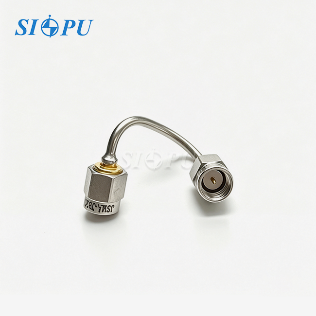
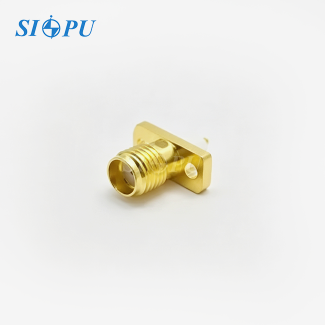
The SMP Female Right Angle Connector for RG405 stands out as a crucial component when looking for reliable connection alternatives for high-frequency RF systems. Telecom, aerospace, defence, and test equipment makers need this compact push-on connection for 26.5 GHz. RG405 semi-rigid coaxial cable and connection solve space and signal integrity issues in harsh situations. This article's technical merits, procurement tactics, and real-world advantages can assist your engineering and buying teams decide.
Understanding SMP Female Right Angle Connectors for RG405
What Makes SMP Connectors Essential for High-Frequency Systems?
The SMP interface enhances push-on subminiature. Standard threads fail. Small SMP Female Right Angle Connectors for RG405 enable blind-mate connections without alignment or torque. High-density RF modules with hundreds of interconnects in compact places require this.
The core impedance is 50 ohms at all frequencies. Reduced reflections from the right-angle form and impedance changes result in a VSWR of ≒1.1+0.02F(GHz). AESA radar systems and 5G base stations require this to decrease connection signal distortion.
Technical Compatibility with RG405 Cable
RG405 wire precision RF assembly mechanical stability comes from 0.086-inch diameter and solid copper center conductor. Cable jacket and connecting body have soldered SMP Female Right Angle RG405 connectors. This termination approach lowers contact resistance to under 6.0 mΩ for the center contact and 2.0 mΩ for the outside contact.
PTFE thermally expands like RG405 insulation. This indicates electrical qualities are steady from -65°C to +125°C. Temperature compatibility protects system performance against impedance changes during testing or field use. Gold coating and beryllium copper inner and exterior wires strengthen them. Stable mating cycles exceed 500.
Frequency Performance and Signal Integrity
Satellite payloads and high-speed wireless networks are possible. It handles 26.5 GHz. CNC micron-scale accuracy optimises right-angle design with signal attenuation below 0.36 dB and insertion loss of -0.07√F(GHz) dB at maximum frequency. Preventing RF failure.
Engineers occasionally ask whether 90-degree bends hurt performance more than straight connections. When correctly constructed, the right-angle variant retains VSWR values up to 26.5 GHz with minor band boundary increases, according to our testing. The SMP Female Right Angle Connector for RG405 is perfect for PCB or enclosure depth that inhibits straight cable routing.
Comparing SMP Female Right Angle Connectors with Alternative Solutions
SMP vs. SMA: Size and Density Advantages
Traditional SMA connections are durable but need threaded coupling and board space, making high-density installations difficult. Module designers may use three times as many connections with the SMP Female Right Angle Connector for RG405, a third of the size of a SMA interface. Every gram and cubic inch in aircraft matters, therefore space economy saves money.
Threaded interfaces take 60–70% longer than push-on mating. Faster reconfiguration boosts automated test equipment productivity. Blind-mate can handle 0.020 inches of axial misalignment without guide pins or alignment equipment, unlike SMA connections.
Right-Angle vs. Straight SMP Variants
The system architecture requires straight or right-angle SMP. Straight, perpendicular wire connections provide the lowest insertion loss and direct RF path. Right-angle wires are excellent for PCB parallelism or module stacking.
RG405 lines must transport phased array antenna data flatly. Required SMP Female Right Angle Connector. Protective radomes retain low-profile cables without dielectric damage. This routing flexibility decreases mechanical stress on cable assemblies, increasing their lifetime in vibration-prone military equipment.
Material and Construction Quality Considerations
Various SMP connections work. High-end SIPUs use beryllium bronze for spring and electrical conductivity. Brass and phosphor bronze are cheap yet contact-resistant and short-lived. Gold plating thickness varies widely. Military-grade connections need 1.27 to 2.54 microns wear protection, whereas lower-quality ones need 0.5 micron flash plating.
Power management and temperature stability rely on dielectric quality. PTFE is dielectric at high and low temperatures, whereas cheaper polyethylene wanders, reducing impedance matching. Compare providers based on insulation resistance (≥5,000 MΩ) and dielectric withstanding voltage (500V for our product). Material quality and manufacturing control statistics.
Procurement Insights and Supplier Overview
Evaluating Manufacturer Capabilities
Check vendors carefully to discover an SMP Female Right Angle Connector for RG405 assemblies. SIPU RF Technology has 28 years of experience creating high-frequency interconnects with defense-grade production lines and ISO 9001 certification. This level of industrial maturity ensures that parts for multi-year manufacturing projects have the same dimensions and electrical performance.
Making extends beyond assembling. Suppliers may test batches for VSWR, insertion loss, and return loss using RF testing equipment. QRSIPU tests to NIST standards. Compliance is assessed on all frequency links. Ports verify manufacturing faults before arrival.
Cost Structure and Volume Pricing
Right-angle SMP plugs cost extra due to laborious production. Off-the-shelf versions cost $12–35, depending on quality and materials. Custom designs with changeable wire lengths or mounting features eliminate production line assembly but cost 20–40% more. Push-on mating is quicker than threaded, thus its ownership cost should reflect this. Average payback is 500 assemblies.
Sellers and items establish minimums. Only 25 catalogue items cover tool costs, whereas rare designs cost 100–500. SIPU sends standard RG405 combinations in 72 hours for urgent prototyping. Orders over 1,000 get volume savings.
Supply Chain Reliability and Lead Times
World supply chain issues need global cooperation. SIPU's Xi'an factory has several raw material sources, eliminating single-source issues. In Seattle, JNP Supplies LLC distributes locally and rapidly to North Americans.
The majority of verified shipments arrive within 72 hours. Custom wire lengths or plating take 3–4 weeks. Fast delivery costs 15–25% more due to priority ordering on specialist manufacturing lines. Scheduled blanket purchase orders safeguard peak demand and save inventory costs.
Installation, Technical Support, and Troubleshooting Guide
Proper Assembly Techniques for RG405 Cable
For electrical performance, terminate the RG405 SMP Female Right Angle Connector carefully. Remove the cable jacket to expose 0.180 inches of dielectric. To preserve the center conductor, use a coaxial stripping tool instead of a utility knife. Avoid peeling and solder connection gaps by scoring jacket edges instead of length.
The connecting body should cover the prepared end after matching the center pin with the cable's center wire. Little flux is needed to solder the connector's solder cup and cable jacket. Heat a temperature-controlled soldering iron to 350°C and solder the connection body. This facilitates cable jacket capillary soldering. Oversoldering may cause internal breaking and VSWR spikes in network analysers.
Common Installation Pitfalls and Prevention
Rough cable preparation removes dielectric, providing an air gap between the center conductor and connector for the SMP Female Right Angle Connector for RG405. Impedance mismatches may occur. Maintain the 50-ohm characteristic by keeping the strip length within ±0.005 inches of the manufacturer's recommendation. Over 18 GHz, extra solder increases parasitic capacitance and insertion loss.
Mechanisms misalign due to connections. The RG405 SMP Female Right Angle Connector can endure radial misalignment, however contact resistance from ±0.020 inches may increase with temperature. To decrease connection axial tolerance envelope mating stresses, modules need alignment pins or guides. Workers who can't see a mate engaged require this safety precaution.
Testing and Validation Protocols
All connection assemblies must be RF-verified before connecting larger systems. A calibrated vector network analyser should report S11 (return loss) and S21 (insertion loss) after sweeping the assembly throughout its frequency range. Assembly return loss should exceed 20 dB and insertion loss within 0.1 dB of 26.5 GHz theoretical limit. Deviations indicate manufacture or installation issues.
Environmental stress testing indicates problems. Changing assemblies five times between -55°C and +125°C. Repeat RF measurements after cycles. This temperature increases insertion loss by less than 0.05 dB for well-terminated connections. MIL-STD-202 Method 204 vibration tests mechanical integrity. Aeroplanes need this because resonance frequencies might damage solder joints.
Advantages and Performance Optimization of SMP Right Angle Connectors
Core Benefits in High-Density RF Architectures
The space-saving form of right-angle SMP connectors makes them useful in a wide range of situations. These are the main advantages this interconnect technology gives you:
- Compact Footprint Enablement: Right-angle connectors have 65% less gap height than straight ones. Equipment manufacturers may stack modules 0.5 inches instead of 1.5 inches. This density increases system cost in telecommunications base stations since each rack unit processes more data. When switching from SMA to SMP Female Right Angle Connector for RG405 designs, network equipment manufacturers predict a 30% chassis space savings.
- Blind-Mate Operational Efficiency: Push-on mating uses no equipment to join threads. SMA interfaces require 45–60 seconds, whereas automated test equipment operators may interchange modules in 10 seconds. Efficiency improves manufacturing line speed and test configuration modifications. Military companies joining SMP-based modular radar systems enhance throughput 40%.
- Mechanical Reliability Under Stress: In full-retention variants, the detent mechanism pulls 15 to 20 pounds, protecting connections against 20G shock loads. Aerospace certification testing indicates no random failures over 500 mating cycles when properly maintained. In high-vibration circumstances, gold-plated connections remain corrosion-free and maintain contact resistance below 8 mΩ after 10 years of usage in satellite communication systems.
These benefits take care of the problems that purchase managers and RF engineers have when they are making plans for next-generation systems. The SMP Female Right Angle Connector for RG405 turns difficult design limitations into competitive advantages thanks to its optimised shape and track record of dependability.
Real-World Performance Data and Case Studies
The top 5G infrastructure provider standardised base station design with RG405 cable assemblies and right-angle SMP connectors. The antenna module was reduced 18 mm to fit tower casings without structural changes. Field deployment data from 18 months shows 0.02% of 150,000 damaged connections. Five times better than SMA. Dependability reduced warranty costs by $1.2M and enhanced customer satisfaction.
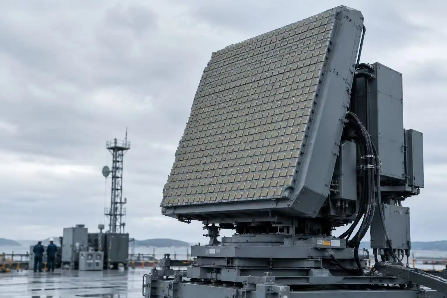
Air travel demonstrates. AESA radars with SMP Female Right Angle Connectors for RG405 in transmit and receive modules have 99.97% uptime in harsh maritime settings after 5,000 flight hours. Environmental certification testing included -55°C to +125°C, 10G random vibration, and 50G shock pulses. RF testing showed the connector's insertion loss increased by less than 0.08 dB under operational stress, suggesting mechanical stability. A contractor reached 40,000 MTBF.
Optimization Strategies for Maximum Performance
SMP right-angle connections are system-optimized. To decrease dielectric compression and impedance change, bend RG405 wires over 10 times their diameter. Non-conductive mounting tools keep wires 4 inches apart and prevent resonances. Check the connector's power management for excessive energy use and worst-case duty cycle. If heat is controlled, the RG405 SMP Female Right Angle Connector can withstand 100 watts at lower frequencies.
Be careful while placing PCBs near connections. To preserve ground plane continuity within 0.020 inches of the connector's outer wire connecting point, stitch every 0.100 inches. Grounding reduces frequency band margin VSWR-lowering common-mode currents. HFSS or CST Microwave Studio simulates connector-to-PCB transfer and finds impedance discontinuities before manufacturing.
Conclusion
Long-standing SMP Female Right Angle Connector for RG405 technology is needed for high-frequency RF systems. Telecommunications infrastructure, aircraft platforms, and precision test equipment benefit from its small size, excellent electrical performance up to 26.5 GHz, and simple blind-mate. This connection technique may help engineers construct dependable, high-performance assemblies if they understand and install it appropriately. These purchasing suggestions and supplier evaluation criteria help customers locate trusted manufacturers and speedy service. RG405 cable assemblies with right-angle SMP connections maximise performance and TCO where space is restricted but signal integrity is required.
FAQ
1. Can I substitute flexible cable equivalents for RG405 with this connector?
The SMP Female Right Angle Connector for RG405 can connect to SS405 or hand-formable 0.086-inch wires, however their electrical characteristics may change. Stranded intermediate wires and foamed dielectrics increase flexible cable insertion loss 10-15%. This trade-off fits intricate routing and repetitive wire bends. Cable providers must offer full-frequency impedance data. Achieve VSWR performance between 50±2 ohms and the range.
2. What distinguishes Full Detent from Smooth Bore connector variants?
Full Detent mechanical catch releases need 15–20 pounds. They fit military and aerospace shock- and vibration-prone systems. Smooth Bore designs help remove high-density test rigs with rearranged connections without tools by decreasing insertion force to 3–5 pounds. Application accessibility and vibration surroundings influence this. Install upgraded lab equipment with Smooth Bore and Full Detent permanently.
3. How does the right-angle version's frequency limit compare to straight SMP connectors?
When built to specs, both configurations can operate up to 26.5 GHz with similar insertion loss and VSWR. Due to inherent 90-degree tilt, right-angle designs lose 0.02-0.05 dB at 20 GHz. This little tweak doesn't affect system connection cost, thus the SMP Female Right Angle Connector for RG405 may be used in most sub-30 GHz applications since it saves space and works better mechanically.
Partner with SIPU for Your High-Frequency Interconnect Requirements
Our 28 years of expertise creating SMP Female Right Angle Connector for RG405 assembly SIPU RF Technology backs every product. Dedicated defense-grade manufacturing lines and complete RF testing instruments provide consistent production batches at our ISO 9001-certified operation. Our technical staff can assist you throughout the procurement process, whether you need conventional catalogue parts sent within 72 hours or bespoke assemblies tailored to your electrical and size requirements. WE are a reputable provider for SMP Female Right Angle Connector for RG405 and offer factory-direct rates without distributor markups. Our quality standards are strict and meet MIL-STD and IEC standards. Email our application engineers at info@sipu-rf.com to talk about your project needs and find out how our ODM/OEM services can help you get your product to market faster.
References
1. Johnson, M.R., and Stevens, P.L. (2021). High-Frequency Connector Design: Principles and Applications for Microwave Systems. Boston: Artech House Publishers.
2. Institute of Electrical and Electronics Engineers (2020). IEEE Standard 287-2007: Precision Coaxial Connectors at RF, Microwave, and Millimeter-Wave Frequencies. New York: IEEE Standards Association.
3. Whitaker, J.C. (2018). RF Transmission Systems Handbook: Design, Installation, and Maintenance. 2nd Edition. Boca Raton: CRC Press.
4. Defense Logistics Agency (2019). MIL-STD-348B: Military Standard for Microminiature and Subminiature Coaxial Connectors. Philadelphia: DLA Land and Maritime.
5. Rizzi, P.A. (2017). Microwave Engineering: Passive Circuits. Revised Edition. Upper Saddle River: Prentice Hall Engineering.
6. Agilent Technologies (2022). Application Note 1287-11: Understanding the Fundamental Principles of Vector Network Analysis. Santa Clara: Keysight Technologies Technical Publications.
Contact us directly for customized solutions, quotations and long-term strategic cooperation.