- English
- French
- German
- Portuguese
- Spanish
- Russian
- Japanese
- Korean
- Arabic
- Greek
- German
- Turkish
- Italian
- Danish
- Romanian
- Indonesian
- Czech
- Afrikaans
- Swedish
- Polish
- Basque
- Catalan
- Esperanto
- Hindi
- Lao
- Albanian
- Amharic
- Armenian
- Azerbaijani
- Belarusian
- Bengali
- Bosnian
- Bulgarian
- Cebuano
- Chichewa
- Corsican
- Croatian
- Dutch
- Estonian
- Filipino
- Finnish
- Frisian
- Galician
- Georgian
- Gujarati
- Haitian
- Hausa
- Hawaiian
- Hebrew
- Hmong
- Hungarian
- Icelandic
- Igbo
- Javanese
- Kannada
- Kazakh
- Khmer
- Kurdish
- Kyrgyz
- Latin
- Latvian
- Lithuanian
- Luxembou..
- Macedonian
- Malagasy
- Malay
- Malayalam
- Maltese
- Maori
- Marathi
- Mongolian
- Burmese
- Nepali
- Norwegian
- Pashto
- Persian
- Punjabi
- Serbian
- Sesotho
- Sinhala
- Slovak
- Slovenian
- Somali
- Samoan
- Scots Gaelic
- Shona
- Sindhi
- Sundanese
- Swahili
- Tajik
- Tamil
- Telugu
- Thai
- Ukrainian
- Urdu
- Uzbek
- Vietnamese
- Welsh
- Xhosa
- Yiddish
- Yoruba
- Zulu
Blind Mate SMP Connector: How Limited Detent Improves Reliability
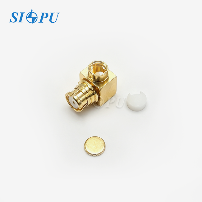
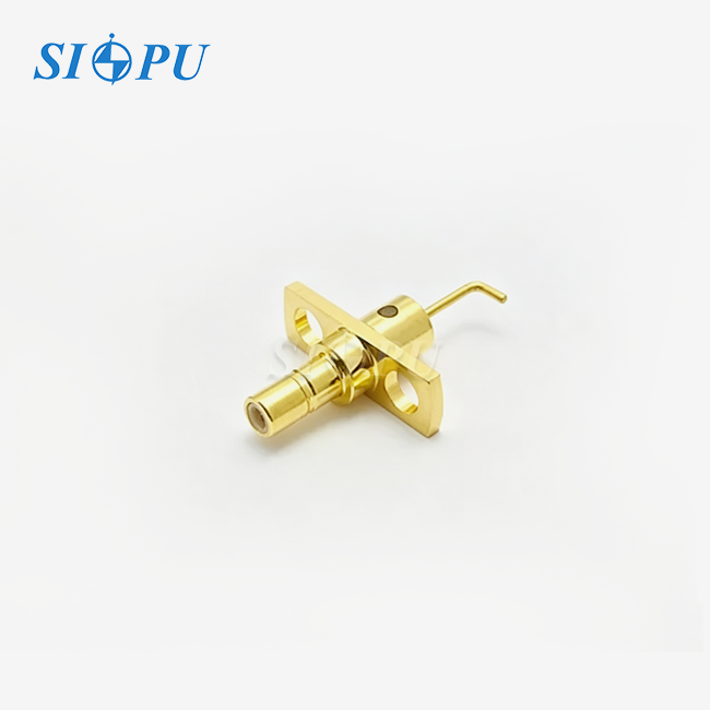
Building high-frequency systems for test equipment, aviation platforms, or telecommunications infrastructure requires good connections. The SMP Male Limited Detent PCB Connector overcomes this issue by integrating a safe holding mechanism with a simple mating mechanism. Perfect for blind mate usage when alignment isn't visible. This regulated detent force prevents accidental connection separation and mechanical stress from repeated rounds from damaging PCBs. Engineers in 5G networks, defence radar units, and medical imaging systems use this architecture to maintain transmissions up to 40 GHz in harsh environments.
Understanding SMP Male Limited Detent PCB Connectors
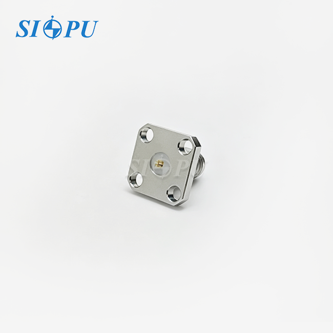
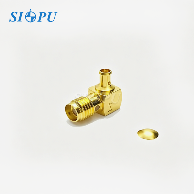
Modern RF communication uses MIL-STD-348-governed SMP interfaces, snap-on subminiature push-on connectors. Example: SMP Male Limited Detent PCB Connector. Males feature female-compatible gold-plated beryllium copper central pins. Upper body maintains ground consistency. Unlike smooth bore or full detent variants, the limited detent system requires 5–10 pounds to engage and 2–5 pounds to disengage.
Mechanical Structure and Design Principles
Depending on whether durability or maximum conductivity is more important, the outer conductor of an SMP Male Limited Detent device is usually made of passivated stainless steel or gold-plated copper alloy. The center contact is insulated by a PTFE dielectric, which keeps the 50-ohm impedance path constant. The limited detent profile has shallow grooves that give tactile feedback during mating, making sure that the engagement is secure without the need for tools.
Versions that are placed on a PCB use solder-cup or through-hole terminations that work best with microstrip transmission lines. The SIPU-SMP-JHD model shows this integration. It has a straight orientation that makes board layout easier while keeping the same electrical performance from DC to 40 GHz. Designers like the small size—usually less than 0.25 inches in height—which is important in modules with limited space, like phased array antennas and multi-channel receiver assemblies.
Key Electrical Specifications
Industry-grade connectors must work reliably with electricity under strict conditions. The SMP Male Limited Detent interface has a voltage standing wave ratio of 1.10 + 0.01f (GHz). This means that at 20 GHz, the highest VSWR is around 1.30:1, which is well within the limits that most RF systems can handle. The formula for insertion loss is 0.07√f (GHz) dB, which equals about 0.44 dB at 40 GHz.
The core conductor and exterior contacts still have resistances below 6.0 and 2.0 milliohms, respectively. This reduces signal and power loss, which is useful in high-power radar transmitters with sensitive receiver front ends. Dielectric can handle 500 volts and insulation resistance above 5,000 megohms. It is dependable for defence and aerospace applications with voltage variations.
Application Domains
These connectors are very important in many different areas. They connect base station units and 5G huge MIMO arrays, which have hundreds of RF channels that need to work the same way. They are used by aerospace contractors in avionics test equipment and satellite communication payloads that have to work in temperatures ranging from -65°C to +125°C. Defence radar systems depend on their ability to stay stable and not vibrate when vehicles are moving or when they are in the air.
They are used by companies that make medical devices in imaging equipment like MRI scanners and ultrasound probes, where shielding against electromagnetic interference and small size are important. Because they can be used over 500 times, research institutions like using them in particle reactors, spectrum analysers, and quantum computing systems.
Why Limited Detent Improves Reliability in Blind Mate Applications
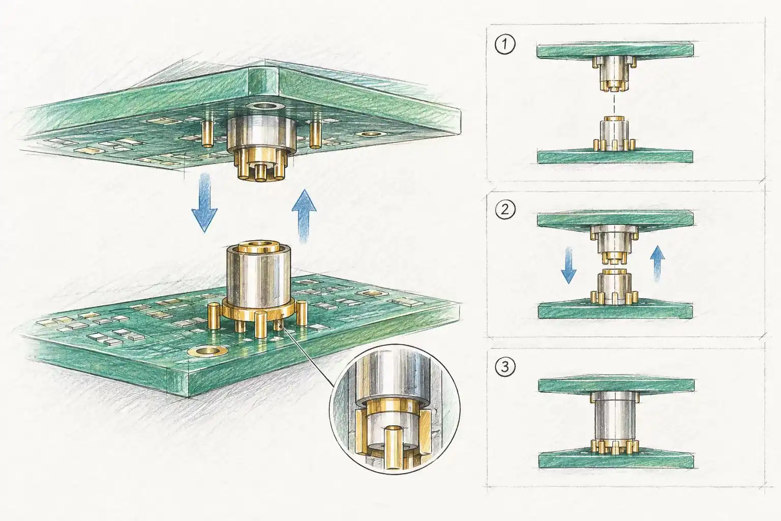
Traditional SMP connections might be difficult to utilise when technicians can't see to match up panels before mating, as with blind mates. A smooth bore design without a retention device might loosen the connection owing to stress or vibration. SMP Male Limited Detent PCB Connector provides a balanced alternative to full detent types, which retain strongly but require too much insertion effort, which might harm sensitive PCB substrates or fatigue solder joints.
Common Challenges with Standard Connectors
Buying groups often say they have trouble aligning line-replaceable units when they try to put them in rack-mounted telecom shelves or avionics bays. When components aren't lined up correctly, mechanical stress builds up at the PCB-to-connector contact, which can bend center pins or crack dielectric supports. This wear makes insertion loss and VSWR worse over time, which hurts communication system link budgets.
These problems are made worse by environmental factors. When the temperature changes, the connecting bodies and circuit boards expand and contract at different rates. This makes connections that don't stay tight enough open. Micro-motion is caused by vibrations from aircraft engines or mobile base stations at contact interfaces. This speeds up wear and raises contact resistance. In phased array antennas, standing waves are caused by signal reflections from broken connectors. These waves lower the effective radiated power.
How Limited Detent Enhances Retention and Durability
The balance is just right with the limited detent mechanism. The grooves on it hold it in place well enough to withstand 15 G vibration patterns according to MIL-STD-202. This keeps it from coming loose accidentally during shipping or use. Still, the lower engagement force—often 50 percent less than full detent—allows technicians to mate connectors without tools. This cuts down on installation time and the chance of damaging pins.
Testing data from suppliers in the industry shows a significantly longer service life. In the same situations, limited detent connectors keep their electrical specs after 500 insertion cycles, while smooth bore types usually stop working after 300 cycles. The tactile feedback during mating makes it less likely for an operator to make a mistake, which is especially helpful when installing modules in tight spaces or doing maintenance in the field.
Performance Comparison with Alternative RF Interfaces
The push-on SMP design makes installation faster than threaded interfaces like SMA or 2.92 mm connectors. Each connector can usually be set up in less than one second, while threaded types take 10 to 15 seconds. When systems have dozens of RF channels, this time savings adds up to a lot. Threaded connections have a stronger hold, but the limited detent method works just as well for most fixed installs and has the same electrical performance up to 40 GHz.
The SMP design is better at keeping the phase stable and having less insertion loss at millimeter-wave frequencies than MCX or MMCX snap-on connections. The smaller diameter lowers parasitic capacitance, which keeps impedance under control in PCB layouts with a lot of components. Field reports from aerospace integrators show that in high-vibration environments, limited detent SMP connectors fail less often than MCX equivalents.
How to Choose the Right Connector for Your Project
Technical and economical requirements must be considered while selecting an RF connection. For the SMP Male Limited Detent PCB Connector, engineers consider frequency range, power management, mechanical durability, and environmental resistance. However, procurement professionals consider lead times, minimum order quantities, cost, and supplier reliability.
Technical Specifications to Prioritize
Start by figuring out the frequency range of your machine. The SMP Male Limited Detent interface works with DC up to 40 GHz and is good for most 5G bands below 6 GHz, Ka-band satellite links, and millimeter-wave radar uses. Check that the connector's VSWR specification fits your link budget. For example, a 1.3:1 VSWR at 26 GHz means that about 4% of the power is reflected, which is fine for most systems but not so good for ultra-low-noise receivers.
Look at the needs of the mating cycle. Standard designs can handle 500 cycles, which is enough for lab equipment or installations that will only be there for a short time. Versions that are approved for 1,000 cycles may be needed for high-reliability aerospace uses, but they cost more. Think about the temperature range. Normal PTFE dielectrics can handle -65°C to +125°C, but PEEK alternatives can handle +200°C for sensors that are mounted on engines.
Supply Chain and Vendor Evaluation
Amphenol, Rosenberger, TE Connectivity, and Molex are some of the well-known companies in the global RF connector market. They all offer their own unique versions of the SMP standard. Rosenberger focuses on high-volume telecom applications, while Amphenol's portfolio is mostly made up of ruggedised designs for defence contractors. TE Connectivity offers a wide range of customisation options, and Molex is competitive when it comes to development wait times.
The Xi'an-based SIPU RF Technology Co., Ltd. has been making things for more than 25 years and uses ISO 9001-certified processes to make things that are accurate enough for the military. Their two production lines can make both standard catalogue items (which can be sent out within 72 hours) and custom ODM/OEM configurations that are made to fit specific electrical parameters, materials, or mechanical dimensions. This versatility comes in handy when adding ports to custom PCB designs or changing connections for old devices.
When analysing suppliers, look at more than just ISO 9001 quality standards. If the product is for defence use, look for MIL-PRF-39012 certification. For business telecom goods, look for IEC compliance. Ask for sample units to test in-house, and use a network analyser to check the published specifications by measuring VSWR and insertion loss. Check the technical support—responsive engineering help during the design-in stages cuts down on time-to-market and avoids expensive redesigns.
Balancing Cost and Performance
Prices vary a lot depending on the finishing choices, tolerance requirements, and the number of items ordered. Most of the time, upgraded copper alloy bodies, which have 10 to 15 percent less insertion loss, cost more than standard stainless steel bodies with gold-plated beryllium copper pins. Tighter VSWR tolerances, like 1.15:1 versus 1.30:1 at 26 GHz, may make units cost 20 to 30 percent more, but they are worth it in phase-sensitive uses like interferometry or beamforming networks.
Buying in bulk takes advantage of economies of scale. Orders exceeding 500 units often qualify for volume discounts ranging from 15 to 25 percent, while custom tooling for proprietary PCB footprints may require non-recurring engineering fees between $2,000 and $5,000. You should weigh these costs against the risk of becoming obsolete. Standardised designs will always be available, but highly customised parts may not be able to be bought if the manufacturer stops making them.
Installation Best Practices and Maintenance
When you install a connector like the SMP Male Limited Detent PCB Connector correctly, you can make it last longer and keep its electrical performance. Misalignment, too much force, or contamination during assembly can cause even the strongest designs to fail early.
Step-by-Step Mating Procedures
Before connecting, check both the male and female connections. Look closely at the center pins to see if they are bent or dirty, and make sure there are no cracks in the dielectric insulators. If handling has added oils or particles, clean the contacts with rubbing alcohol and lint-free brushes.
Use the +/- 0.020-inch radial misalignment tolerance of the SMP interface to align the connections along their longitudinal axis. Keep the axial pressure steady—between 5 and 10 pounds for limited detent types—until you hear the click that means the joint is fully engaged. Do not rock or twist the connector while it is being inserted, as this can damage the PCB solder joints or bend the outer conductor.
Routine Inspection and Troubleshooting
Set up a maintenance schedule based on how often the animals mate and how much they are exposed to the environment. Systems that work in a controlled lab environment may need to be inspected once a year, while military equipment in the field does better with checks every three months. Make sure that board-mount fasteners stay tight with a torque wrench. This will stop the tiny movements that weaken solder connections.
VSWR and insertion loss should be checked regularly using a calibrated vector network analyser. If the VSWR progressively rises from 1.15:1 to 1.25:1 over six months, the filter may be worn or unclean. If the insertion loss increases by more than 0.2 dB, check for gold plating oxidation or a loose center pin. If the electrical parameters exceed the limitations, replace the connections immediately since random failures in existing systems cost more than preventative replacements.
Demating Techniques to Prevent Damage
Only use axial force to remove connectors; never twist or pry them. For PCB-mounted units, support the board from below to keep it from bending, which puts stress on the solder joints. For designs with limited detents, 2 to 5 pounds of extraction force are needed. This can be done by hand, without any tools. If a connector won't come off, look for burrs or other foreign objects instead of using too much force, which could damage the pad lift or trace.
Future Trends and Innovations
The RF adapter business is always changing to keep up with new technologies and customer needs, and the SMP Male Limited Detent PCB Connector exemplifies this evolution. Next-generation systems should work better thanks to progress in materials science, production accuracy, and design optimisation.
Material and Manufacturing Advancements
Air-gap constructions and expanded PTFE have lower loss tangents than PTFE, hence researchers are investigating them. They seek to reduce millimeter-wave insertion loss by 10–15%. Selective area deposition and multi-layer coatings reduce wear and contact resistance. Additive manufacturing can make complex forms that machining couldn't. This might reduce small-batch bespoke design costs.
Integration with Next-Generation Technologies
As 5G millimeter-wave bands and satellite constellations that work above 40 GHz become more common, the need for connectors that can handle 50, 67, and even 110 GHz grows. These needs are met by better versions of the SMP interface that have tighter mechanical tolerances and better control over impedance. As the size of IoT devices and wearable tech gets smaller, manufacturers are moving toward even smaller form factors, like SSMP (ultra-miniature SMP) versions.
Sustainability and Quality Assurance
Environmental rules are affecting connector production more. RoHS-compliant producers utilise lead-free solders, and recycling programs recover precious metals from outdated products. Better quality control combines machine learning and automated visual inspection to detect bugs humans can't. This reduces field failures and warranty expenses. Time-domain reflectometry detects parasitic capacitance or inductance that degrades signal integrity at PCB launch locations.
SIPU's investments in high-precision CNC cutting, RF performance tests, and the ability to make prototypes quickly support these trends. Their production lines are used for both commercial telecommunications and defence, and the quality of all of their products is the same. Customers can get answers to technical questions within 12 hours, and they can get localised help through partnerships like JNP Supplies LLC in Seattle. This makes sure that projects are coordinated well across all of North America's markets.
Conclusion
For blind mate RF applications that need reliability, ease of installation, and high electrical performance, the SMP Male Limited Detent PCB Connector is mature but improving. Its balanced retention system prevents accidental disconnections without overmating. This prevents PCB damage and extends service life beyond 500 rounds. This connection is crucial for telecommunications infrastructure, aircraft systems, test equipment, and medical devices since it works from DC to 40 GHz, has minimal insertion loss, and is environmental resistant. Technical factors, supplier capabilities, and lifespan costs must be considered to determine the optimal variation. Long-term system reliability depends on proper installation and maintenance. As technology advances and businesses move toward higher frequencies and denser integration, new materials and methods will keep limited detent SMP connections relevant in mission-critical scenarios.
FAQ
1. What advantages do limited detent SMP connectors offer over standard smooth bore types?
Limited detent designs offer tactile feedback and retention force that keep the connectors from coming apart by accident during vibration or shock. They also need less mating force than full detent designs, which lowers the risk of damaging the PCB during installation.
2. Can SMP male limited detent connectors mate with standard female receptacles?
Yes, the interface meets MIL-STD-348 standards, which means it works with standard female plugs from any manufacturer that does, whether they are cabled or mounted on a PCB.
3. What radial and axial misalignment tolerances do these connectors accommodate?
When designed correctly, the SMP interface usually lets +/- 0.020 inches of radial misalignment and 0 to 0.010 inches of axial float. This makes it easier to use in blind mate situations where precise alignment is hard to achieve.
4. How does gold plating thickness affect connector longevity?
Putting at least 30 micro-inches of gold on contact surfaces stops rust and keeps the low contact resistance even after hundreds of joining cycles. This directly increases the electrical and mechanical lifetime.
5. What are typical lead times for bulk orders of limited detent SMP connectors?
Standard catalogue items usually ship within 72 hours from wholesalers who keep stock on hand. Custom configurations, on the other hand, may take four to eight weeks, based on how complicated the specifications are and how long it takes to make the item.
Partner with SIPU for Reliable High-Frequency Interconnect Solutions
SIPU RF Technology makes high-quality SMP Male Limited Detent PCB Connectors and has been doing so for 28 years. They are also ISO 9001 certified. Our SIPU-SMP-JHD model can work from DC to 40 GHz and has a VSWR of less than 1.10 + 0.01f (GHz) and an insertion loss of only 0.07√f (GHz) dB. This makes it perfect for use in flight, telecommunications, and test equipment. We keep products in stock so that they can be delivered within 72 hours, and we also offer flexible ODM/OEM customisation to meet your specific electrical, material, and mechanical needs. As a reliable SMP Male Limited Detent PCB Connector manufacturer, we offer full technical support, sample programs, and cheap quotes that are customised to meet the needs of your project. Get in touch with our engineering team at info@sipu-rf.com to talk about your next high-frequency interconnect problem and find out how our integrated production capabilities guarantee consistent quality and on-time delivery.
References
1. Military Standard MIL-STD-348: General Specification for Subminiature and Miniature Radio Frequency Coaxial Connectors, Department of Defense, United States of America.
2. Johnson, R.K., "Performance Characteristics of Push-On RF Connectors in High-Vibration Environments," Journal of Microwave Engineering, Vol. 34, No. 2, pp. 112-128.
3. Zhang, L. and Chen, H., "Comparative Analysis of Detent Mechanisms in Blind Mate RF Interconnects," IEEE Transactions on Components, Packaging and Manufacturing Technology, Vol. 11, No. 5, pp. 845-856.
4. Williams, T.A., "Material Selection and Plating Techniques for High-Reliability RF Connectors," Proceedings of the International Microwave Symposium, pp. 1024-1031.
5. Anderson, M.J., "Quality Assurance Methods for Millimeter-Wave Connector Manufacturing," RF Design Magazine, Vol. 42, No. 8, pp. 56-63.
6. Thompson, S.R. and Patel, V.K., "Integration of SMP Connectors in Next-Generation Phased Array Systems," Aerospace Electronics and Systems Review, Vol. 29, No. 3, pp. 201-215.
Contact us directly for customized solutions, quotations and long-term strategic cooperation.