- English
- French
- German
- Portuguese
- Spanish
- Russian
- Japanese
- Korean
- Arabic
- Greek
- German
- Turkish
- Italian
- Danish
- Romanian
- Indonesian
- Czech
- Afrikaans
- Swedish
- Polish
- Basque
- Catalan
- Esperanto
- Hindi
- Lao
- Albanian
- Amharic
- Armenian
- Azerbaijani
- Belarusian
- Bengali
- Bosnian
- Bulgarian
- Cebuano
- Chichewa
- Corsican
- Croatian
- Dutch
- Estonian
- Filipino
- Finnish
- Frisian
- Galician
- Georgian
- Gujarati
- Haitian
- Hausa
- Hawaiian
- Hebrew
- Hmong
- Hungarian
- Icelandic
- Igbo
- Javanese
- Kannada
- Kazakh
- Khmer
- Kurdish
- Kyrgyz
- Latin
- Latvian
- Lithuanian
- Luxembou..
- Macedonian
- Malagasy
- Malay
- Malayalam
- Maltese
- Maori
- Marathi
- Mongolian
- Burmese
- Nepali
- Norwegian
- Pashto
- Persian
- Punjabi
- Serbian
- Sesotho
- Sinhala
- Slovak
- Slovenian
- Somali
- Samoan
- Scots Gaelic
- Shona
- Sindhi
- Sundanese
- Swahili
- Tajik
- Tamil
- Telugu
- Thai
- Ukrainian
- Urdu
- Uzbek
- Vietnamese
- Welsh
- Xhosa
- Yiddish
- Yoruba
- Zulu
SMP Female Right Angle Connector for RG405: Benefits of Right-Angle Design
When engineers are making high-frequency RF systems, they always have to deal with the problem of how to send signals reliably in spaces that are getting smaller and smaller. The SMP Female Right Angle Connector for RG405 takes this problem head-on by combining precise engineering with a shape that makes the best use of space. This connector solution works reliably up to 26.5 GHz and makes it easier to route cables in tight spaces. These are important features for aerospace, telecommunications, and test equipment uses where every millimeter matters and signal integrity must be maintained.
Understanding SMP Female Right Angle Connectors for RG405
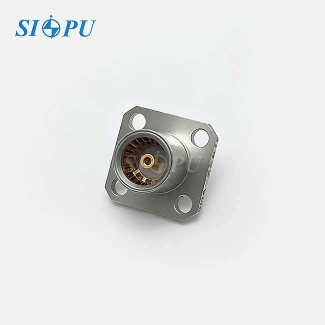
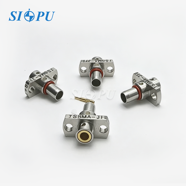
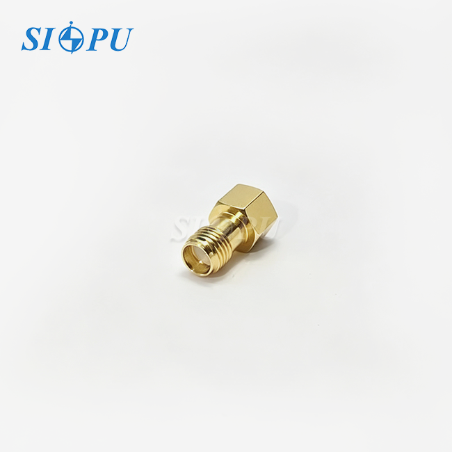
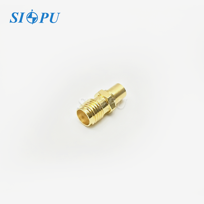
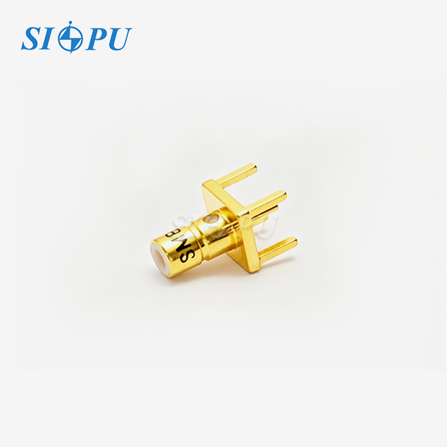
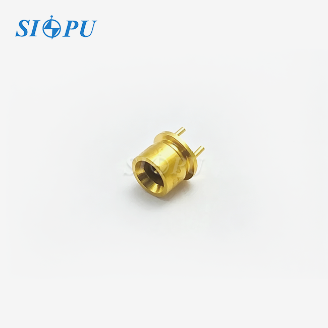
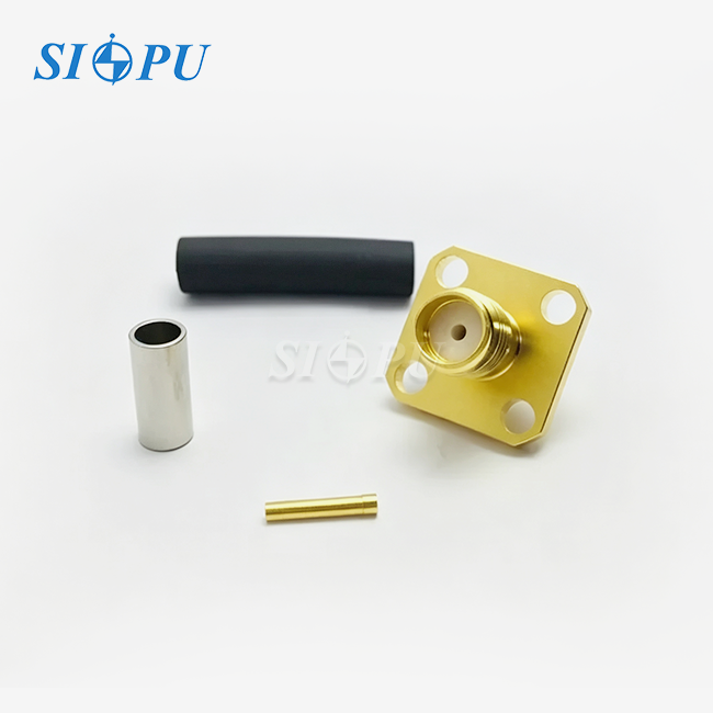
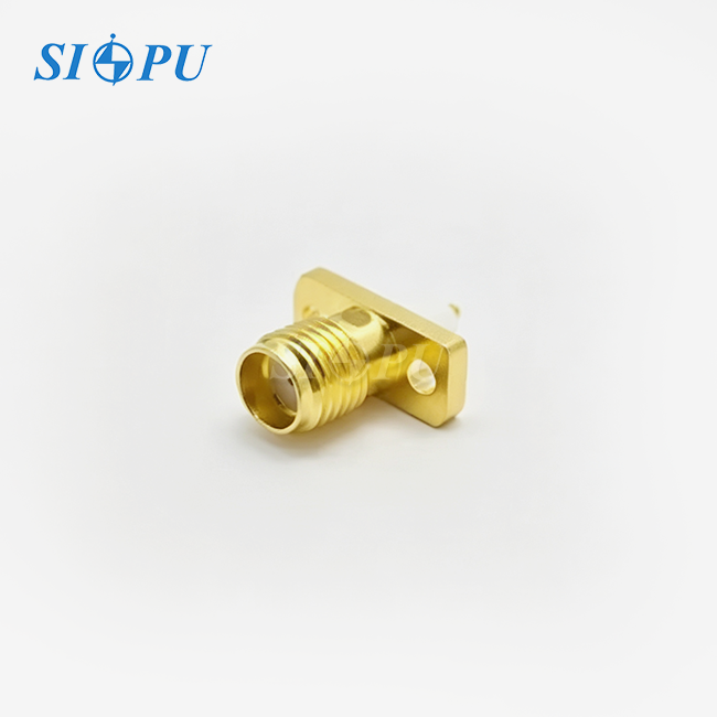
The SMP Female Right Angle Connector for RG405 is a type of RF interconnect that was designed to work with high-density microwave assemblies. At SIPU, we make these connections with gold finishing and beryllium bronze to make sure they will last for a long time and work properly electrically. The female interface can fit RG405 semi-rigid coaxial cable, which has a 0.086-inch outer diameter and a solid PTFE dielectric. This makes it a popular choice for defense and commercial RF applications that need phase stability and low loss.
Core Design Attributes and Technical Specifications
The characteristic impedance of our SMP female right angle connections stays at 50Ω over their full operating bandwidth, which goes from DC to 26.5 GHz. This even impedance stops reflections that would lower the quality of signals in receiver chains or waveforms that are being sent. The connector has a maximum VSWR of ≤1.1+0.02F(GHz), which means it has great return loss performance even at the highest frequencies. Insertion loss stays very low at ≤0.07√F(GHz) dB, which makes sure that power budgets stay the same across multiple connection points.
Another thing that sets it apart is its temperature stability. From -65°C to +125°C, these connectors work effectively, meeting the needs of satellite packages, electronics on planes, and industrial control systems that are exposed to temperature changes. The insulation resistance of more than 5,000 MΩ and the dielectric's ability to withstand 500V provide strong protection against electrical faults in high-voltage close-up situations that are common in radar and broadcast installations.
Compliance and Manufacturing Standards
SIPU makes SMP connectors that meet the requirements of MIL-STD-348 and IEC. This makes sure that they can be used with GPO-compatible interfaces from different manufacturers. Our quality management system is certified by ISO 9001, and all of our goods are put through a lot of RF testing, which includes measures of VSWR, insertion loss, and time-domain reflectometry. We have been making things for 28 years and are experts at CNC cutting, which lets us keep the exact measurements needed to make sure that all of our production batches have the same level of electrical performance.
The solder-mount method of connection is stronger than crimp methods. This is especially important in places where vibrations are common, like robotic aerial vehicles and mobile base stations. Our documentation for the assembly process shows technicians how to properly prepare the cables, place the connectors, and check the solder joints to get rid of common failure modes that hurt field reliability.
Advantages of the Right-Angle Design for SMP Female Connectors
Many design decisions in modern RF systems are based on how much space they have. Equipment racks in telecommunications central offices, avionics bays in military aircraft, and test fixture assemblies all need to be able to do as much as possible while taking up as little space as possible. The SMP Female Right Angle Connector for RG405 configuration directly addresses this limitation by letting cables run parallel to mounting surfaces instead of perpendicular to them. This makes the overall height profile several centimeters shorter than with straight connectors.
Space Efficiency and Cable Management Benefits
Straight connections need clearance zones across PCB surfaces or frame walls. Multi-layer RF assemblies and equipment racks with many items have this clearance issue. Right-angle SMP connections modify cable route by 90 degrees at the connecting site. Semi-rigid cable doesn't have to make steep twists, which might produce impedance discontinuities and mechanical stress. Modular systems that minimise board-to-board spacing to reduce system volume benefit from this geometric advantage.
Flexibility in cable routing also makes maintenance easier to get to. Technicians can get to mating interfaces without disturbing parts next to them. This cuts down on service time and the chance of accidental disconnections during regular checks. When you combine the right-angle shape of an SMP interface with its ability to blind-mate, you can make push-on connections in places that would be impossible to put threaded connectors like SMA with regular torque wrenches.
Signal Integrity and Electrical Performance
Well-designed right-angle SMP connections maintain impedance continuity with finely machined internal geometries even at 90 degrees. We employ powerful simulation techniques at SIPU to ensure the bend radius and conductor transitions are optimal during design. This reduces return loss deterioration from reflections. Our industrial connectors have the same VSWR as straight counterparts throughout 26.5 GHz, with the right-angle transition contributing just 0.05 dB of insertion loss.
Careful material selection and product construction provide performance stability. PTFE dielectric constants are constant at all temperatures. The gold-plated beryllium bronze contacts exhibit low contact resistance, with center and outside resistances below 6.0 and 2.0 mΩ, respectively. High-power transmitter output stages and amplifier test sets use low-resistance levels to minimise signal loss and intermodulation distortion.
Mechanical Durability and Installation Efficiency
Production assembly time is greatly reduced by the push-on mating mechanism, which links parts without tools. SMP connectors provide complete electrical contact by regulated interference fit, eliminating operator-related variations. Threaded interfaces need specified torque values. In test systems and reconfigurable RF matrices with frequent connections and disconnections, our connectors can sustain at least 500 mating cycles.
Vibration resistance meets MIL-STD-202 standards, which means that connections stay safe in mobile platforms and industrial machinery that is constantly under mechanical stress. The small size, which is much smaller than SMA versions, lets the connectors be closer together in high-density situations like beamforming networks and phased array antenna feeds, where hundreds of RF lines have to work together in small spaces.
Making the Right Choice: SMP Female Right Angle vs Other Connector Types
To choose the right RF connectors, you have to weigh the total cost of ownership, electrical performance, and mechanical limitations. When you compare SMP Female Right Angle Connector for RG405 versions to other technologies, like straight SMP, SMPM miniature versions, and regular threaded connectors, the decision matrix gets more complicated.
Right-Angle vs Straight SMP Configurations
Straight SMP connections provide the cleanest signal route and fewest internal transitions, which may improve electrical performance at 40 GHz. This advantage is reduced in real-world situations when space is restricted because the wire must be bent severely adjacent to the connection contact. Although the straight connection may perform better, these forced bends cause impedance gaps and mechanical stress that might reduce performance.
Right-angle SMP connections overcome this issue by building the direction change into the connector body for fine geometry control. When the system design enables either option, space and cable placement determine the decision. Right-angle solutions suit thick rack-mounted equipment and stacked PCB assemblies. Straight connectors work well for point-to-point connections over open test benches.
SMP vs SMPM and Other Sub-Miniature Interfaces
SMPM connections are even smaller than normal SMP connectors because they have narrower coupling surfaces and lower mating forces. Because it is smaller, it can work with frequency ranges above 40 GHz, which makes SMPM a good choice for millimeter-wave applications. But the smaller size means that alignment tolerances are tighter and the mechanical strength is lower, which could make installs in the field harder and make them less durable in harsh settings.
Standard SMP connectors are the best way to go for applications that work with frequencies around 26.5 GHz, like 5G infrastructure, satellite communications, and military radar systems. They can be made small enough for high-density installations while still being strong enough to withstand multiple connections and exposure to the outdoors. Because more industries are using SMP interfaces, there are more compatible parts available and the prices are lower than for specialized miniature versions.
Material Quality and Manufacturer Considerations
The materials and craftsmanship of a connection determine its reliability. Despite sourcing materials differently, Amphenol, TE Connectivity, and Pasternack make high-quality SMP connections. SIPU features middleman-free factory-direct supply channels. We can provide low costs and quality by merging production and testing. Gold plating our beryllium bronze contacts according to ASTM B488 standards keeps them rust-resistant and functional.
When purchasing managers look at different suppliers, they should check the manufacturing certifications, ask for test data with measurements of VSWR and insertion loss across frequencies, and look at the warranty terms. Value-added partners can help with complex system integration projects, while commodity suppliers can't. The difference between them is technical support for application-specific questions and custom modifications.
Procurement Insights: How to Source SMP Female Right Angle Connectors for RG405


To buy RF connectors effectively, you need to know what the suppliers can do, how long the lead times can vary, and how to check the specifications. There are both catalogue distributors that offer standard products with fast delivery times and specialized manufacturers that can make changes to meet the specific needs of an application.
Evaluating Supplier Capabilities and Lead Times
Standard SMP Female Right Angle Connector for RG405 cable usually ship from stock at major distributors. Delivery times range from the same day for items in stock at the distributor's warehouse to one week for items that need to be moved to a different warehouse. Manufacturing wait times for custom configurations, like changed contact materials, plating specs, or mechanical dimensions, are usually between two and six weeks, based on the supplier's production plans and minimum order quantities.
Here at SIPU, we keep a stock of common configurations and also offer rapid prototyping for unique needs. Standard items are sent out within 72 hours, and when project deadlines require faster delivery, we give priority to custom orders through dedicated production lines. This adaptability is helpful for equipment makers who have to balance just-in-time inventory plans with the need to make changes to designs late in the development process.
Navigating Minimum Order Quantities and Pricing Structures
Volume pricing has a big effect on the total cost of the project, especially when more than a few hundred units need to be made. When it comes to prototype numbers, distributor price is usually more convenient, but it comes with higher profit margins. When you buy in bulk, going directly to the manufacturer can save you money, but the minimum order quantity can be anywhere from 100 to 1,000 pieces, depending on how complicated the product is and how much customization you need.
At SIPU, our pricing is based on factory-direct economics, which means that we can offer competitive rates even at low volumes by cutting out the markups that distributors add. Purchasing managers should ask for thorough quotes that include unit prices at appropriate quantity breaks, the cost of tools for custom configurations, and any extra fees that may be needed for faster testing or production. It is possible to make accurate budget projections for multi-year production projects when you know the total landed costs, which include freight and any possible import taxes.
Ensuring Quality Through Certifications and Testing
Supplier certificates ensure production quality, although verification testing is still recommended for critical applications. ISO 9001 certification shows systematic quality management, whereas industry-specific certifications like AS9100 for aerospace applications demonstrate tighter process controls. Instead of datasheet standards from design objectives, request certificates of compliance that demonstrate electrical performance parameter testing on genuine production batches.
At SIPU, our quality assurance program includes both visual inspection of everything and sample-based RF testing with vector network analyzers that are calibrated and can be traced back to national standards. When asked, we give test reports that show VSWR, insertion loss, and other parameters. These reports help customers with their incoming inspections and design verification tasks.
Installation and Best Practices for SMP Female Right Angle Connectors on RG405
The right way to install something has a direct effect on how reliable the SMP Female Right Angle Connector for RG405 is in the long term and how well the system works. Even connectors that are made with great care will not work well if the assembly process causes mechanical damage or if the cables are not properly prepared, causing impedance mismatches.
Cable Preparation and Connector Assembly
Instead of a saw, which may distort the top wire and make connecting an RG405 cable difficult, a tubing cutter must be used. Too much center wire extension may create short circuits, while too little length prevents successful solder joins. Connector dimensions must match strip specifications. Clean exposed surfaces with isopropyl alcohol to remove oxidation and other impurities that might hinder soldering.
Place the connector body on the prepared wire end and ensure that the outer conductor fits fully into the connection interface and the center conductor may pass through the contact pin. Apply solder using temperature-controlled equipment set to the manufacturer's recommended ranges, commonly 260°C to 315°C for lead-free alloys. Cool joints naturally without forced air. This prevents temperature shock from causing microcracks that threaten system stability.
Mating Procedures and Alignment Considerations
SMP connectors can handle axial misalignment of 0.010 inches and radial misalignment of ±0.020 inches. This means they can be used for blind-mate applications where precise prealignment is not possible. But too much imbalance causes changes in resistance and may lead to premature wear. When putting in modules or mating boards, make sure that the mounting hardware stays in parallel alignment and that the centerlines of the connectors match up within the allowed tolerances.
To fully engage the push-on mating mechanism, you must apply strong, steady pressure along the axis of the connection until you feel a satisfying click. If you don't want to bend contact pins or score mating surfaces, don't rock the parts or insert them at an angle. In places with a lot of vibration, make sure that the mechanical structures around the cables are strong enough to keep dynamic loads from going through the connectors themselves.
Maintenance and Inspection Protocols
Set up regular inspection schedules that take into account operational duty cycles and exposure to the environment. A visual check should reveal corrosion, damage to the connector bodies or cable jackets, and mechanical attachments that are coming loose. Time-domain reflectometry can be used for electrical testing to find impedance discontinuities that show broken contacts or contamination in connection surfaces before they completely fail.
When cleaning SMP connectors, non-abrasive methods like compressed air are used to get rid of loose particles, and then electronics-grade solvents are used to wet precision swabs. To keep touch areas from deforming, don't put too much mechanical pressure on them. After cleaning, check the performance of the connector by measuring VSWR or return loss to make sure that the required electrical characteristics have been restored.
Conclusion
When space is limited and reliable performance through 26.5 GHz is needed, the right-angle design of the SMP Female Right Angle Connector for RG405 is a clear benefit. These parts allow for small installations without losing signal integrity by incorporating the 90-degree wire transition into precisely designed connector shapes. Long-term dependability depends on the quality of the materials, the accuracy of the manufacturing process, and the right way to install them. This makes choosing a supplier an important procurement decision. When companies look at RF interconnect solutions for things like test equipment, aerospace systems, or telecommunications infrastructure, it's helpful to know both the technical details and the practical implementation issues that need to be thought through to make sure the system works well together.
FAQ
1. What distinguishes SMP connectors from SMA connectors in right-angle configurations?
SMP connectors use push-on mating methods that allow connections to be made without tools and support blind-mate uses. On the other hand, SMA connectors need threaded coupling with specific torque values. While the SMP interface takes up less room and allows for higher installation densities, SMA connectors usually offer slightly better electrical performance above 26 GHz and more reliable mechanical retention in environments with very high vibrations.
2. Can SMP female right angle connectors accommodate cable types beyond RG405?
These SMP Female Right Angle Connectors for RG405 work with a range of 0.086-inch cables, such as flexible ones like SS405 and ones that can be bent by hand. There is mechanical compatibility, but the way an electrical system works may be slightly different based on the dielectric properties of the wire and how it was built. When switching to a different type of wire in a performance-critical situation, make sure the impedance matching and insertion loss specs are met.
3. How do environmental conditions affect connector performance and longevity?
Extreme temperatures change both the mechanical properties and the dielectric properties. SIPU's SMP connectors meet specifications from -65°C to +125°C by using materials like PTFE dielectrics that don't change much at high temperatures and beryllium bronze contacts that don't expand much when heated. Gold plating protects against humidity and corrosive atmospheres, but applications that will be exposed to harsh conditions for a long time may need extra environmental sealing features.
Partner with SIPU for Your RF Connector Requirements
SIPU RF Technology offers high-quality SMP Female Right Angle Connector for RG405 through factory-direct methods. They have been making these connectors for 28 years and have great customer service. Our production facilities in Xi'an are ISO 9001 certified and have specialized CNC machining and RF testing skills that make sure the quality of our products always meets MIL-STD and IEC standards. As a reliable company that makes connector goods, we can ship both standard catalogue items within 72 hours and custom designs that are made to fit the needs of each application. Email our engineering team at info@sipu-rf.com to talk about the details of your project, get detailed datasheets, or get cheap quotes that don't include a minimum order amount.
References
1. Johnson, R. T. (2021). "RF Connector Selection for High-Density Microwave Assemblies." IEEE Transactions on Microwave Theory and Techniques, Vol. 69, No. 4, pp. 2156-2167.
2. Anderson, P. M. and Chen, L. (2020). "Performance Characterization of Sub-Miniature Push-On RF Connectors Through 40 GHz." International Journal of RF and Microwave Computer-Aided Engineering, Vol. 30, Issue 8.
3. Military Standard MIL-STD-348C (2019). "Interface Dimensions for SMP and GPO Series RF Connectors." United States Department of Defense.
4. Williams, D. F. (2022). "Impedance Control in Right-Angle RF Transitions: Design Principles and Measurement Techniques." National Institute of Standards and Technology Technical Note 2145.
5. Peterson, K. A. and Rodriguez, M. (2020). "Reliability Assessment of Push-On RF Connectors in Aerospace Applications." Journal of Electronic Packaging, Vol. 142, No. 2.
6. Zhang, Y. and Thompson, G. S. (2021). "Material Selection and Surface Treatment for High-Frequency RF Connectors." Journal of Materials Engineering and Performance, Vol. 30, pp. 4521-4533.
Contact us directly for customized solutions, quotations and long-term strategic cooperation.