- English
- French
- German
- Portuguese
- Spanish
- Russian
- Japanese
- Korean
- Arabic
- Greek
- German
- Turkish
- Italian
- Danish
- Romanian
- Indonesian
- Czech
- Afrikaans
- Swedish
- Polish
- Basque
- Catalan
- Esperanto
- Hindi
- Lao
- Albanian
- Amharic
- Armenian
- Azerbaijani
- Belarusian
- Bengali
- Bosnian
- Bulgarian
- Cebuano
- Chichewa
- Corsican
- Croatian
- Dutch
- Estonian
- Filipino
- Finnish
- Frisian
- Galician
- Georgian
- Gujarati
- Haitian
- Hausa
- Hawaiian
- Hebrew
- Hmong
- Hungarian
- Icelandic
- Igbo
- Javanese
- Kannada
- Kazakh
- Khmer
- Kurdish
- Kyrgyz
- Latin
- Latvian
- Lithuanian
- Luxembou..
- Macedonian
- Malagasy
- Malay
- Malayalam
- Maltese
- Maori
- Marathi
- Mongolian
- Burmese
- Nepali
- Norwegian
- Pashto
- Persian
- Punjabi
- Serbian
- Sesotho
- Sinhala
- Slovak
- Slovenian
- Somali
- Samoan
- Scots Gaelic
- Shona
- Sindhi
- Sundanese
- Swahili
- Tajik
- Tamil
- Telugu
- Thai
- Ukrainian
- Urdu
- Uzbek
- Vietnamese
- Welsh
- Xhosa
- Yiddish
- Yoruba
- Zulu
SMP Male Limited Detent PCB Mount Connectors — a Practical Guide
If you work with high-frequency RF systems, you already know how much a single connector decision can affect system performance. The SMP male limited detent PCB mount connector sits at the intersection of signal integrity, mechanical reliability, and assembly efficiency — making it one of the most practical choices for engineers designing phased array, radar, and test equipment platforms today. This guide walks you through everything you need to know before you buy.
Understanding SMP Male Limited Detent PCB Mount Connectors
What Is an SMP Male Limited Detent PCB Mount Connector?
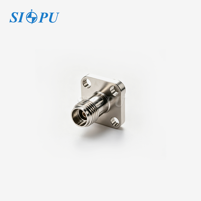
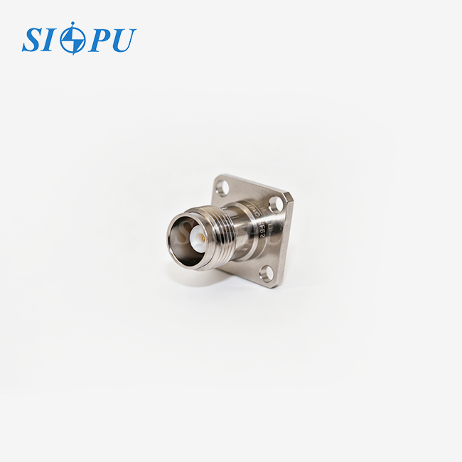
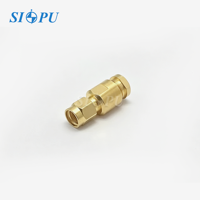
This is a sub-miniature push-on RF interface called the SMP male limited detent PCB mount connector. It is made for board-level microwave links up to 40 GHz. "Limited detent" is in the middle of the SMP retention system, between "smooth bore" (low retention) and "full detent" (high retention). It provides a moderate level of mechanical hold. This balance makes it possible for modules to stay attached during mild vibration and shock without the need for special tools for extraction, which is helpful in PCB layouts that are very dense.
Key Electrical and Mechanical Specifications
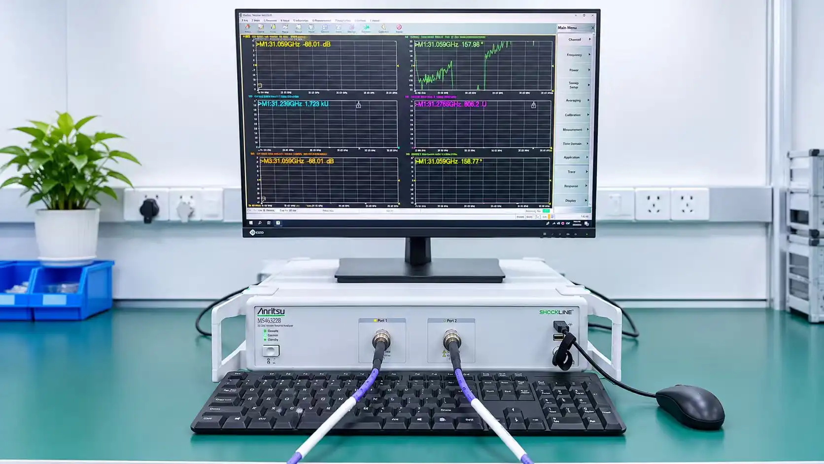
The SIPU-SMP-JHD6 type works from DC to 40 GHz and has a characteristic impedance of 50 Ω. The VSWR value is -1.5, and the insertion loss is -0.07√F(GHz) dB. The force to engage is 45 N, and the force to separate is 9 N. The link can handle at least 500 joining cycles, works in temperatures ranging from -65 °C to +125 °C, and has an insulation resistance of at least 5,000 MΩ at 500 V. The center conductor is made of beryllium bronze that has been coated in gold. The outer housing is made of passivated stainless steel that has a PTFE dielectric.
SMP Male vs. SMP Female: Fitting Compatibility
The SMP male limited detent PCB mount connector has a center pin and fits into a female receptacle on a board or module that is opposite it. It's cheaper to not have to redo a board if the gender orientation is correct during layout. The male PCB-mount version works with blind-mate setups, which means that the connector lines itself automatically when the module is inserted, without any visual help. This is a common feature in modular backplane designs.
Comparing SMP Male Limited Detent Connectors With Other Connector Types
Limited Detent vs. Full Detent vs. Smooth Bore
Every SMP retention level is good for a different set of priorities. Here is a direct way to compare them:
- Smooth bore: Lowest engagement force; best for frequent disconnection and lab bench use. Offers minimal vibration resistance.
- Limited detent (this connector): Medium retention; hand-disconnectable; handles moderate vibration without specialized tools. The preferred choice for telecom infrastructure and phased array modules where boards are periodically replaced.
- Full detent: Maximum retention; resists severe vibration in airborne or naval systems; requires a removal tool, which slows maintenance cycles.
When you choose the wrong retention level, it can either damage PCB pads during servicing or cause the field to disconnect. For most production settings, the SMP male limited detent PCB mount connector is just what engineers need.
How SMP Compares to SMA and MMCX at High Frequency
SMA connectors can handle up to 18 GHz in most cases. 6 GHz is what MMCX connections can do. The SMP male limited detent PCB mount adapter has a 40 GHz limit, and both of them have the same small size. Tenths of a millimeter is how much space there is on millimeter-wave phased array boards, so SMP's sub-miniature body that can blind-mate is simply a better fit than threaded or snap-lock options.
Selection Criteria for B2B Procurement
When bulk-producing RF push-on connectors, three factors always play a role in the choice:
- VSWR tolerance: Higher VSWR at board transitions creates signal reflection that degrades system noise figure. Confirm rated performance across the full operating band, not just a midband figure.
- Plating specification: Gold plating on beryllium bronze contacts, as used in the SIPU-SMP-JHD6, prevents oxidation and maintains low contact resistance (center ≤6.0 mΩ; outer ≤2.0 mΩ) over extended service life.
- Batch consistency: In phased array systems with hundreds of connector sites per board, batch-to-batch variation in engagement force or gold thickness creates yield problems at scale.
Procurement Guide for SMP Male Limited Detent PCB Mount Connectors
Supplier Evaluation and Lead Times
Getting the SMP male limited detent PCB mount connector from a well-known company greatly lowers the risk in the supply chain. SIPU RF Technology has been around since 1998 and is ISO 9001 certified. They have separate production lines for both standard and custom SMP versions. Standard stock ships within 72 hours, but custom configurations are given more time to be made. For buyers in North America, SIPU's local partner JNP Supplies LLC in Seattle, Washington, offers quick project planning and help in the area.
Pricing Factors and Negotiation Levers
The unit price for precision RF push-on connectors includes the cost of the materials (beryllium bronze and gold plating), the tolerances needed for the machining process, and the cost of testing. When you commit to buying more than 1,000 units, you can usually get lower prices. For engineering review, mixed-SKU sample orders can be placed before committing to production amounts. This is an important step for any new board design where first-article testing must happen before mass purchase.
Compliance and Export Considerations
For export categorization purposes the SMP connections are ECCN 3A001.b. Buyers purchasing for military or dual-use projects should contact their trade compliance team before placing cross-border purchases to see whether an export license is required. SIPU production batches are tested to be RoHS compliant to fulfill the requirements.
Installation and Maintenance Best Practices
PCB Layout and Soldering Guidelines
Key factor impacting first pass yield is getting the pad geometry perfect. The SIPU-SMP-JHD6 PCB solder-mount shape is intended to allow the solder to adhere extremely effectively while soldering using both reflow and wave soldering. When lead-free reflow forms are employed, the PTFE insulation will maintain its shape up to roughly 260 °C. Compare pad sizes to the manufacturer’s recommended footprint drawing before soldering. Pads that are not properly aligned produce impedance gaps at the board transition point that will cause VSWR to increase over the norm of ≤1.5.
Common Installation Errors and How to Avoid Them
There are three mistakes that most PCB-mount push-on connectors make that cause them to fail in the field:
- Excessive axial misalignment: Any air gap increase between mating reference planes raises VSWR and introduces phase instability. Keep axial gap within specified tolerance.
- Cold solder joints: Insufficient thermal mass during soldering leaves voids under the ground tabs, weakening mechanical retention and increasing outer contact resistance.
- Forcing misaligned mating: Blind-mate assemblies require panel alignment guides. Forcing an off-axis connection deforms the center contact and degrades impedance continuity.
Taking these three things into account during the design review stage stops most connection failures on the production line and keeps SMT yield rates high on boards with a lot of components.
Ongoing Maintenance and Inspection
After deployment, check the mating interfaces every so often as part of regular maintenance. Look for wear or dirt on the gold touch areas. Check that the separation force stays between 9 N and 10 N; a big drop could mean that the stop is wearing out. During system calibration, if VSWR readings go up, the connector interface is often the first place that should be checked before the RF source or cable is thought to be the problem.
Benefits and Practical Applications of SMP Male Limited Detent Connectors
The SMP male limited detent PCB mount link has clear benefits in a number of high-demand areas. These are the main things that make this device good:
- Phased array antenna systems: High-density RF module stacking benefits from blind-mate capability and moderate retention. Individual boards can be swapped during maintenance while adjacent modules remain connected.
- Military radar and EW platforms: The PCB-mount architecture eliminates cable stress points. The limited-detent hold maintains signal path integrity through shock and vibration profiles typical of airborne and naval environments.
- Automated test equipment: Semiconductor and RF test systems require frequent mating cycles at millimeter-wave frequencies. The limited-detent mechanism extends connector service life compared to full-detent alternatives in high-cycling test environments.
These benefits directly lead to lower replacement costs, fewer production stops, and stable signal quality over the equipment's working lifetime. These are the things that procurement teams always put first when making decisions about high-reliability sourcing.
Conclusion
The SMP male limited detent PCB mount connector is an important part of current RF system design. It provides stable blind-mate connectivity from DC to 40 GHz with a retention level that balances resistance to vibration with ease of serviceability in the field. It can work in temperatures ranging from -65 °C to +125 °C and has a VSWR of −1.5. These features make it a good choice for phased array, radar, and test equipment systems. Picking the correct connector from a reliable, checked supply chain helps protect both board yield and long-term system performance.
FAQ
1. What distinguishes limited detent from full detent in SMP connectors?
Limited detent provides lower retention and withdrawal forces, enabling hand disconnection without special tools. Full detent maximizes vibration resistance but typically requires a dedicated removal tool. For most telecom and phased array applications, limited detent offers sufficient hold with better serviceability.
2. Does this connector support blind-mating?
Yes. The SMP male limited detent PCB mount connector is specifically designed for blind-mate scenarios where visual alignment during insertion is impossible, such as modular backplane systems.
3. What is the rated lifecycle?
The connector is rated for a minimum of 500 mating cycles, provided alignment remains within the specified radial and axial tolerance limits throughout service.
4. Is it compatible with lead-free reflow soldering?
Yes. The PTFE dielectric withstands standard lead-free reflow profiles reaching approximately 260 °C without performance loss.
5. How does axial misalignment affect signal performance?
Increased air gap between male and female reference planes raises VSWR and introduces phase instability. Maintaining specified alignment tolerances preserves the rated ≤1.5 VSWR performance.
Source Your SMP Male Limited Detent PCB Mount Connector From SIPU
SIPU RF Technology has been making precise RF interconnects for more than 25 years. These are used by engineers in 5G, defense, and test equipment. Our SMP male limited detent PCB mount connector source can produce products that are ISO 9001 certified and deliver them within 72 hours. We also offer mixed-sample prices for engineering trials and full NDA support for OEM projects. You can email our technical team at info@sipu-rf.com or go to sipuconn.com to ask for a sample, see the full list of specs, or talk about a custom setup for your next board design.
References
1. IEEE Transactions on Microwave Theory and Techniques — IEEE, 2021.
2. MIL-PRF-39012: Connectors, Coaxial, Radio Frequency, General Specification — U.S. Department of Defense, 2020.
3. MIL-STD-348: Radio Frequency Connector Interfaces for MIL-PRF-39012 — U.S. Department of Defense, 2019.
4. Microwave Journal: PCB-Level RF Connector Technology for 5G and Phased Array Systems — Microwave Journal, 2022.
5. IPC-7351: Generic Requirements for Surface Mount Design and Land Pattern Standard — IPC, 2017.
6. RF and Microwave Circuits, Measurements, and Modeling — Chang, K. & Bahl, I., Wiley, 2008.
Contact us directly for customized solutions, quotations and long-term strategic cooperation.