- English
- French
- German
- Portuguese
- Spanish
- Russian
- Japanese
- Korean
- Arabic
- Greek
- German
- Turkish
- Italian
- Danish
- Romanian
- Indonesian
- Czech
- Afrikaans
- Swedish
- Polish
- Basque
- Catalan
- Esperanto
- Hindi
- Lao
- Albanian
- Amharic
- Armenian
- Azerbaijani
- Belarusian
- Bengali
- Bosnian
- Bulgarian
- Cebuano
- Chichewa
- Corsican
- Croatian
- Dutch
- Estonian
- Filipino
- Finnish
- Frisian
- Galician
- Georgian
- Gujarati
- Haitian
- Hausa
- Hawaiian
- Hebrew
- Hmong
- Hungarian
- Icelandic
- Igbo
- Javanese
- Kannada
- Kazakh
- Khmer
- Kurdish
- Kyrgyz
- Latin
- Latvian
- Lithuanian
- Luxembou..
- Macedonian
- Malagasy
- Malay
- Malayalam
- Maltese
- Maori
- Marathi
- Mongolian
- Burmese
- Nepali
- Norwegian
- Pashto
- Persian
- Punjabi
- Serbian
- Sesotho
- Sinhala
- Slovak
- Slovenian
- Somali
- Samoan
- Scots Gaelic
- Shona
- Sindhi
- Sundanese
- Swahili
- Tajik
- Tamil
- Telugu
- Thai
- Ukrainian
- Urdu
- Uzbek
- Vietnamese
- Welsh
- Xhosa
- Yiddish
- Yoruba
- Zulu
SSMB Female Right Angle Connector for RG316 Cable: What to Know
If you work in RF engineering or communications test equipment procurement, you already know how much a single connector choice can affect your entire system. The SSMB female right angle connector for RG316 cable is one of those components that quietly determines whether your prototype passes or fails. This article covers what this connector does, why it matters, how to choose and install one correctly, and what to look for when sourcing from a manufacturer. Whether you are designing a test module, a GPS receiver assembly, or a compact industrial RF instrument, the information here will help you make a confident decision.
Understanding SSMB Female Right Angle Connectors and RG316 Cables
What Is an SSMB Connector?
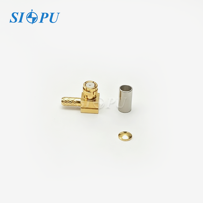
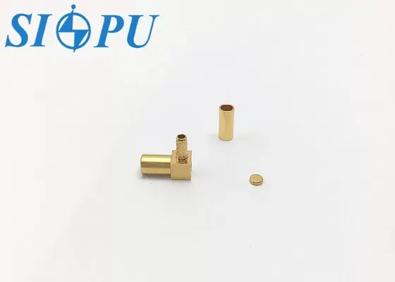
"SSMB" stands for "Sub-Sub-Miniature B." It is a very small RF connector that connects with a snap-on mating interface instead of a threaded coupling. The SSMB body is smaller than the standard SMB connector, which makes it ideal for high-density PCB layouts and small test assemblies. The female right angle version routes the cable at a right angle to the mating axis, which is very important when there isn't much room for vertical movement.
Why RG316 Cable?
The 50-ohm coaxial wire RG316/U has a silver-plated copper-clad steel inner conductor and a FEP jacket on the outside. Its small diameter (about 2.5 mm) and ability to withstand high temperatures make it the ideal wire for RF systems that are limited in room and need to work at 3 GHz or higher. It makes a small, low-loss data path that works well in a wide range of temperatures when paired with the right SSMB female right angle connector for RG316 cable.
Key Electrical Differences vs. Straight Connectors
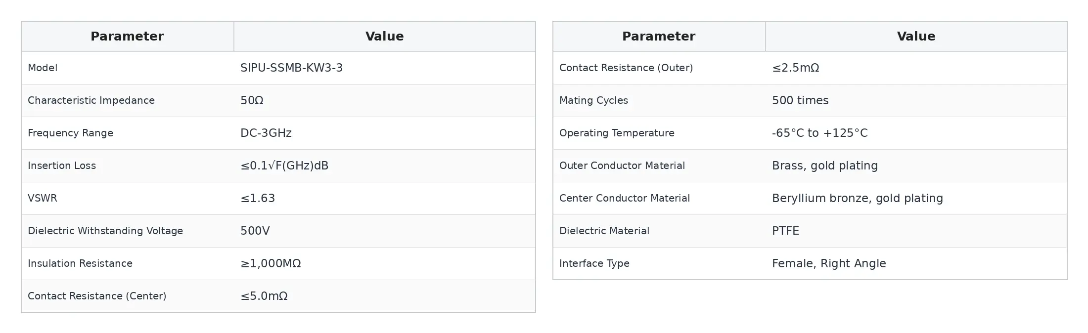
A straight connection doesn't make a logical break, but a right angle connector does. With careful machining and the right impedance control, that break stays well within accepted ranges. This SIPU model, SIPU-SSMB-KW3-3, has a VSWR of ≒1.63 and an insertion loss of 0.1√F(GHz) dB from DC to 3 GHz. These numbers show that the 90-degree shape doesn't affect the integrity of the signal for most communications test applications when it's made correctly.
Key Advantages and Applications of SSMB Right Angle Connectors with RG316
The SIPU-SSMB-KW3-3 solves three engineering issues that come up a lot in designing communications test equipment and GPS modules: limited board space, stress on cable routing, and differences in performance from batch to batch. In terms of technology, these are the main benefits of this connector:
- 90-degree space-saving geometry: The right angle body allows cable exit parallel to the PCB surface, eliminating the need for a cable bend radius outside the enclosure. This directly reduces mechanical stress on the RG316 jacket and inner conductor, extending assembly service life.
- Gold-plated brass outer conductor with beryllium bronze center contact: Gold plating on the brass body provides corrosion resistance and low contact resistance. The beryllium bronze center pin maintains consistent spring tension through all 500 rated mating cycles, keeping contact resistance below 5.0 mΩ at the center and 2.5 mΩ at the outer conductor.
- PTFE dielectric with broad thermal range: PTFE insulation keeps electrical characteristics stable from -65°C to +125°C, covering both laboratory and outdoor deployment conditions without degradation.
These benefits directly address the issues that most RF procurement engineers bring up: VSWR drift between batches, connector failure after repeated mating, and supply inconsistency during the change from prototype to production.
The connection is used in four different areas. In communication test equipment, it sends signals between PCB test modules that are stacked so close together that there is almost no room for vertical movement. The small size and 50-ohm match keep radio feed losses to a minimum in GPS and BeiDou receiver systems. In aircraft and electronics, the snap-lock interface doesn't let vibrations cause it to separate. In test, measurement, and automation instruments used in industry, the connector's thermal stability covers the temperature range of most units that are used in the field.
How to Select and Install an SSMB Female Right Angle Connector on RG316 Cable
Choosing Between Right Angle and Straight
In some cases, the cable needs to exit parallel to the mounting surface. In these cases, a straight connector would require the cable to be bent very tightly within a few millimeters of the termination. When the cable exits perpendicular to the board and there is space above the connector, an SSMB connector that is straight is the right choice. When you force a wire to bend near a straight connection, the return loss goes up and the conductor could break over time.
Female vs. Male Selection
A male SSMB pin can fit into a female SSMB connection. The connector on the cable end of most PCB-mounted test kits is female, while the connection on the board or instrument end is male. Before you buy, check your PCB or instrument panel to see what gender the mating contact is. Mismatch here leads to immediate problems with assembly and pushes back schedules for prototypes.
Installation Steps for RG316 Termination
There is a set order for properly terminating the SSMB female right angle connector for RG316 cable. Take off about 5 mm of the RG316 jacket to reveal the braid. Then, fold the braid back over the jacket, cut away 2 mm of the inner insulator to reveal the center conductor, and lightly tin the center conductor. For the outer ferrule, use a calibrated hex crimp tool to keep the measurements correct. For the solder cup on the center contact, use a fine-tip soldering station that has been heated to about 300°C. Once everything is put together, look it over visually, then do a continuity check and, if you have the right tools, a TDR sweep to make sure there isn't a break in the resistance at the crimp junction.
Procurement Guide: Sourcing SSMB Female Right Angle Connectors for RG316 Cable
Evaluating a Manufacturer's Credentials
When sourcing an SSMB female right angle connector for RG316 cable supplier, prioritize manufacturers that operate under ISO 9001 certification and can demonstrate compliance with RoHS and, where relevant, MIL-STD-202 environmental test standards. Request documented test data covering VSWR, insertion loss, mating cycle endurance, and salt spray results. A credible manufacturer will provide these as part of standard product documentation rather than as a special request.
Managing Lead Times and Batch Consistency
For engineering teams running short procurement cycles of one to three months, connector availability from stock is not optional. Batch-to-batch consistency matters as much as initial sample performance. Specify that production lots must be accompanied by incoming inspection records covering plating thickness, contact resistance, and dielectric withstanding voltage at 500 V. This step alone eliminates most prototype failure events tied to connector variation.
Pricing and Bulk Order Strategy
Connectors in the SSMB family are priced in tiers based on order quantity. For engineering sample stages, mixed-SKU pricing across small quantities is standard practice. Moving to a single-source SSMB female right angle connector for RG316 cable manufacturer early in the design cycle, rather than switching at production, keeps tooling and qualification costs low and preserves delivery priority when volumes ramp.
Conclusion
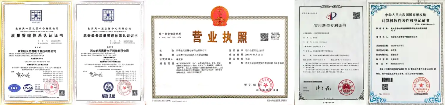
Choosing the correct SSMB female right angle connector for RG316 cable is critical for reliable RF performance in tight electronic systems. The SIPU-SSMB-KW3-3 is a practical solution for communication test equipment, GPS modules and industrial RF instruments, including a 50 ohm characteristic impedance, working frequency DC to 3 GHz and space-saving 90-degree construction. Engineers should check connection gender, cable compatibility, electrical parameters, and termination requirements before purchase to guarantee a good fit and consistent performance. Working with an experienced manufacturer also ensures batch uniformity and supply dependability for OEM projects and bulk buying. SIPU RF Technology provides connection solutions with more than 25 years of RF manufacturing expertise, in-stock availability and 72-hour dispatch.
FAQ
1. What is the frequency range of the SIPU-SSMB-KW3-3?
The connector operates from DC to 3 GHz with a characteristic impedance of 50 ohms. This range covers the majority of communications test, GPS, and industrial RF applications.
2. How does SSMB compare to MMCX for RG316 assemblies?
Both use snap-on interfaces, but SSMB derives from the SMB mechanical series and provides a more rigid mechanical interface. MMCX uses a rotating snap-on design that allows some axial rotation after mating. For high-vibration environments, SSMB offers a more stable connection.
3. Is the connector compatible with RG174 cable?
The SSMB female right angle connector for RG316 cable is optimized for RG316/U. RG174 has a similar outer diameter but a different conductor geometry. Using RG174 may require a different crimp ferrule size to achieve proper retention force.
4. Does the gold plating meet RoHS requirements?
Yes. Each production batch at SIPU undergoes RoHS compliance testing. The gold-over-brass plating process uses lead-free chemistry in accordance with current environmental standards.
5. What is the dielectric withstanding voltage?
The connector is rated at 500 V. Insulation resistance is ≥1,000 MΩ, verified through batch-level dielectric withstanding voltage testing.
Connect with SIPU for Your SSMB Connector Needs
SIPU RF Technology was established in 1998 and has its main office in Xi'an, China. They have the SSMB female right angle connector for RG316 cable in stock and can send it within 72 hours. They also have special production lines for making custom orders. SIPU serves communications test, GPS module, and industrial RF OEM customers all over North America. They are ISO 9001 certified, RoHS compliant, and have been making precision RF products for over 25 years. You can email us at info@sipu-rf.com or go to sipuconn.com to get samples, look at product specs, or talk to an RF interconnect engineer directly.
References
1. IEC 61169-14: Radio-Frequency Connectors — Part 14: Sectional Specification for rf coaxial connectors of Series SMB. International Electrotechnical Commission, 2013.
2. MIL-STD-202H: Test Methods for Electronic and Electrical Component Parts. U.S. Department of Defense, 2015.
3. Pozar, D. M. Microwave Engineering, 4th ed. Wiley, 2011.
4. RoHS Directive 2011/65/EU (Recast): Restriction of Hazardous Substances in Electrical and Electronic Equipment. European Parliament and Council, 2011.
5. Montrose, M. I. EMC and the Printed Circuit Board: Design, Theory, and Layout Made Simple. IEEE Press, 1999.
6. RF Industries. "Coaxial Cable Reference Guide for RF Connector Selection." Microwave Journal, 2019.
Contact us directly for customized solutions, quotations and long-term strategic cooperation.