- English
- French
- German
- Portuguese
- Spanish
- Russian
- Japanese
- Korean
- Arabic
- Greek
- German
- Turkish
- Italian
- Danish
- Romanian
- Indonesian
- Czech
- Afrikaans
- Swedish
- Polish
- Basque
- Catalan
- Esperanto
- Hindi
- Lao
- Albanian
- Amharic
- Armenian
- Azerbaijani
- Belarusian
- Bengali
- Bosnian
- Bulgarian
- Cebuano
- Chichewa
- Corsican
- Croatian
- Dutch
- Estonian
- Filipino
- Finnish
- Frisian
- Galician
- Georgian
- Gujarati
- Haitian
- Hausa
- Hawaiian
- Hebrew
- Hmong
- Hungarian
- Icelandic
- Igbo
- Javanese
- Kannada
- Kazakh
- Khmer
- Kurdish
- Kyrgyz
- Latin
- Latvian
- Lithuanian
- Luxembou..
- Macedonian
- Malagasy
- Malay
- Malayalam
- Maltese
- Maori
- Marathi
- Mongolian
- Burmese
- Nepali
- Norwegian
- Pashto
- Persian
- Punjabi
- Serbian
- Sesotho
- Sinhala
- Slovak
- Slovenian
- Somali
- Samoan
- Scots Gaelic
- Shona
- Sindhi
- Sundanese
- Swahili
- Tajik
- Tamil
- Telugu
- Thai
- Ukrainian
- Urdu
- Uzbek
- Vietnamese
- Welsh
- Xhosa
- Yiddish
- Yoruba
- Zulu
How Retention Force Shapes SMP Male Limited Detent PCB Mount Connector Design
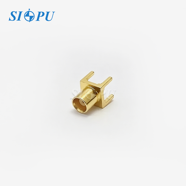
Retention force is the defining mechanical variable in any SMP male limited detent PCB mount connector. It governs whether a mated pair stays locked under vibration, whether a technician can service it by hand, and whether the RF signal path remains stable across thousands of cycles. At SIPU RF Technology, the SIPU-SMP-JHD6 is engineered to deliver 45 N engagement force and 9 N separation force — a calibrated balance that suits 5G phased array boards, radar modules, and automated test equipment alike. Understanding how that force is set, and why it matters, helps engineers and procurement teams make better sourcing decisions.
Understanding SMP Male Limited Detent PCB Mount Connectors
There are three types of retention in the SMP connector family: smooth bore (low retention), limited detent (mid retention), and full detent (high retention). Each level is best for a different type of field.

What Makes Limited Detent Different
A limited detent interface makes a small groove on the female socket so that the male pin can snap into place when it is engaged. This makes the paired pair "click" and has a moderate hold—strong enough to stop vibrations but not so strong that a technician needs a tool to take it off. In this case, the SIPU-SMP-JHD6 acts exactly like this: 45 N to mate and 9 N to release.
Core Datasheet Specifications
With a characteristic resistance of 50 Ω, the SIPU-SMP-JHD6 SMP male limited detent PCB mount connector works from DC to 40 GHz. It is stable from −65 °C to +125 °C, the insertion loss is ≤0.07√F(GHz) dB, the insulation resistance is ≥5,000 MΩ, and the VSWR stays at ≤1.5. The minimum number of cycles for mating is 500.
Materials and Construction
The middle wire is made of gold-plated beryllium bronze (BeCu), which was picked because it keeps its springiness even when the temperature changes. The outside body is made of gold-plated brass and passivated stainless steel. This combination of materials keeps the contact resistance low (≤6.0 mΩ on the center pin and ≤2.0 mΩ on the outer pin) and keeps the materials from oxidizing in damp places.
Impact of Retention Force on Connector Design and Performance
There is more to retention force than just making things work better. In high-frequency PCB circuits, it has a direct effect on signal purity, service life, and environmental durability.

Signal Integrity Under Cycling Stress
The touch areas are put under small amounts of stress every time they mate. If the retention force is too low, contacts can micro-arc when they vibrate, which causes impedance discontinuities. If it is too high, the plating wears out faster. The limited detent specification aims for a zone where 500 rated cycles don't cause any VSWR degradation that can be seen. IEC (IEC 61169-2) published test results for RF connectors that show that controlled retention force is directly related to stable return loss over time.
Vibration and Shock Resistance
PCBs in phased array antenna modules can be affected by vibration loads from fans that cool the module, placing it on a car, or platforms in the air. A smooth-bore SMP connection can back out when there is a steady 20 G vibration, but a limited detent hold of 9 N separation force can handle those loads without wearing out the cable. With the SIPU-SMP-JHD6's PCB solder-mount design, cable-related leverage is less of a concern. Instead, mechanical stress is distributed across the solder joints rather than concentrated on the contact spring.
Temperature Cycling and Environmental Durability
Repeated temperature changes can affect the spring properties and contact stability of RF connectors. Material selection is therefore important for maintaining consistent retention force during thermal cycling. Gold-plated BeCu maintains its spring properties better than phosphor bronze over repeated thermal cycles, making it a preferred contact material for high-reliability SMP connectors. The passivated stainless steel housing makes the connector more resistant to corrosion, which makes it last longer in coastal or humid environments.
Comparing SMP Male Limited Detent Connectors with Alternatives
|
Electrical property |
Temperature range |
-65~+125℃ |
||
|
Characteristic impedance |
50Ω |
Frequency range |
DC-40GHz |
|
|
Dielectric withstanding voltage |
500V |
VSWR |
≤1.1+0.01F(GHz) |
|
|
Insulation resistance |
≥5000MΩ |
Insertion loss |
≤0.07 |
|
|
Contact resistance |
Center conductor |
≤6.0mΩ |
Mechanical property |
|
|
Outer conductor |
≤2.0mΩ |
Durability |
500cycle |
|
|
Limited detent |
Engagement force |
45N |
Separation force |
9N |
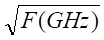 dB
To pick the right retention level, you need to know what the real trade-offs are between the different types of connectors.
Here is a direct comparison of the four options that RF engineers look at most often:
- SMP Smooth Bore: Lowest engagement and separation force. Easy to mate and unmate, but vulnerable to back-out under vibration. Suitable only for bench-top or low-vibration enclosures.
- SMP Limited Detent (e.g., SIPU-SMP-JHD6): Medium retention — 45 N in, 9 N out. Hand-serviceable without tools. The best balance for modular telecom and defense boards that need periodic maintenance.
- SMP Full Detent: High retention for severe shock environments. Requires an extraction tool, which can damage dense PCB layouts during removal. Preferred for sealed airborne units with rare service intervals.
- SMB Connectors: Snap-on design, lower frequency ceiling (~4 GHz typical), and larger footprint. Not competitive for millimeter-wave or high-density board stacking.
Each of these choices has a different effect on the assembly. Limited detent connectors are the best of both worlds because they protect data lines without making upkeep hard. That serviceability margin cuts down on downtime and rework costs directly for 5G AAU board assemblies where RF engineers swap modules during field trials.

Procuring SMP Male Limited Detent PCB Mount Connectors: What You Need to Know
Good connector procurement goes beyond the datasheet. Supply chain reliability, qualification samples, and NDA protection matter as much as the electrical specification.
Supplier Qualification Criteria
When evaluating an SMP male limited detent PCB mount connector supplier, procurement teams should verify ISO 9001 certification, batch-level traceability, gold plating thickness via XRF inspection, and retention force consistency across lots. SIPU operates under ISO 9001 and tests every production batch for dielectric withstanding voltage (500 V), insulation resistance, and RoHS compliance. Plating adhesion is verified at batch level to catch process drift before shipment.
Pricing Structure and Sample Policy
SIPU offers mixed-quantity sample pricing alongside volume pricing tiers. Engineering trial orders can be placed at sample quantities with full production-grade specifications, which lets procurement teams run component comparison testing before committing to a supply arrangement. Lead times for standard stock items are 72 hours; custom pad layouts or material variants ship on dedicated production lines with priority logistics.
Compliance and Export Considerations
SMP connectors fall under ECCN 3A001.b. Export orders require standard EAR classification review. For customers with IP sensitivity, SIPU provides NDA agreements before sharing custom design files or proprietary PCB pad layouts. Note: the SIPU-SMP-JHD6 achieves VSWR ≤1.5, which differs from higher-grade SMP variants rated ≤1.10 + 0.01f. For applications above 26 GHz where this difference matters, SIPU's engineering team will discuss the performance impact with you directly before order confirmation.
Best Practices for Assembly and Performance Optimization
Installing a connection correctly is what turns a well-specified one into a safe system part.
Before putting it together, make sure that the PCB pad dimensions exactly match the solder-mount footprint of the connector. The SIPU-SMP-JHD6 has gold-plated surfaces that allow for both human soldering and automatic reflow. The PTFE insulator can handle lead-free reflow profiles up to about 260 °C without changing its shape.
When installing, the axial position of plugs that fit together should stay within 0.5 mm of each other. Misalignment along the x-axis makes the effective air gap between reference planes bigger, which increases VSWR and causes phase instability. If the connections on your board stack are blind-mate, the fixture design should limit the radial float to the connector's rated tolerance before locking down the mechanical design.
Once everything is up and running, use a VNA to check the insertion loss and return loss over the whole operating band. If a batch of connectors shows VSWR above the ≤1.5 limit during incoming inspection, they should be marked before the board is put together. Finding this problem during incoming QC is much cheaper than fixing a soldered board.
Conclusion
In a limited detent connection, the retention force is the variable that links mechanical engineering to RF performance. Too low, and the contacts come back out when the motor shakes. Too high, and tools used for upkeep hurt thick PCB design. There are 45 N of engagement and 9 N of separation goals for the SIPU-SMP-JHD6 SMP male limited detent PCB mount connector. This is a specification that works for 5G phased arrays, radar modules, and test systems. With its gold-plated BeCu contacts, passivated stainless steel housing, and frequency limit of 40 GHz, this connector gives RF engineers a reliable, serviceable link that stays in good shape for 500 rated cycles.
FAQ
1. What is the difference between limited detent and full detent in SMP connectors?
With a separation force of 9 N on the SIPU-SMP-JHD6, limited detent offers modest retention, letting you separate it by hand without any tools. Full detent provides the best vibration resistance, but it needs an extraction tool, which can damage the PCB during service.
2. Does this connector support blind-mate applications?
Yes. The SIPU-SMP-JHD6 is made for blind-mate situations in modular backplanes where it's not possible to see which components are lined up. Within its rated tolerance window, the connector can handle both radial and axial misalignment.
3. What is the rated service life?
At least 500 mating cycles must be completed, as long as the axial and radial alignment stays within the specifications for the entire life of the connector.
4. Is the connector compatible with lead-free reflow soldering?
Yes. Standard lead-free reflow profiles can heat the PTFE dielectric up to about 260 °C without changing its shape or electrical properties.
5. How does axial misalignment affect VSWR?
VSWR goes up and phase instability happens when the air gap between joined reference planes gets bigger. The ≤1.5 VSWR rate stays the same across the whole DC–40 GHz band as long as the orientation stays within the allowed range.
Request Samples or a Quote from SIPU — Your Trusted SMP Male Limited Detent PCB Mount Connector Manufacturer
Since 1998, SIPU RF Technology has been making high-precision RF connectors. Standard configurations of the SIPU-SMP-JHD6 can be shipped within 72 hours from stock. Custom pad layouts can be made on separate production lines. Our engineering team replies within 12 hours and offers technical help that is protected by an NDA from the first question to mass production. To get SMP male limited detent PCB mount connector samples, mixed-lot prices, or a straight consultation on your 5G or radar board design, email us at info@sipu-rf.com or visit sipuconn.com.
References
-
IEC 61169-2: Radio-frequency connectors — Part 2: Established reliability general test procedures. International Electrotechnical Commission, 2018.
-
MIL-PRF-39012: Connectors, Coaxial, Radio Frequency, General Specification for. U.S. Department of Defense, 2017.
-
MIL-STD-348B: Interface Standard for RF Connector Interfaces for MIL-PRF-39012, MIL-PRF-55339, MIL-PRF-49142, MIL-DTL-17, and MIL-DTL-83517. U.S. Department of Defense, 2014.
-
Pozar, D. M. Microwave Engineering, 4th ed. Wiley, 2011.
-
Sturdivant, R., & Harris, M. Transmit Receive Modules for Radar and Communication Systems. Artech House, 2015.
-
IEEE Standard for Precision Coaxial Connectors (DC to 110 GHz). IEEE Std 287-2007. IEEE, 2007.
Contact us directly for customized solutions, quotations and long-term strategic cooperation.