- English
- French
- German
- Portuguese
- Spanish
- Russian
- Japanese
- Korean
- Arabic
- Greek
- German
- Turkish
- Italian
- Danish
- Romanian
- Indonesian
- Czech
- Afrikaans
- Swedish
- Polish
- Basque
- Catalan
- Esperanto
- Hindi
- Lao
- Albanian
- Amharic
- Armenian
- Azerbaijani
- Belarusian
- Bengali
- Bosnian
- Bulgarian
- Cebuano
- Chichewa
- Corsican
- Croatian
- Dutch
- Estonian
- Filipino
- Finnish
- Frisian
- Galician
- Georgian
- Gujarati
- Haitian
- Hausa
- Hawaiian
- Hebrew
- Hmong
- Hungarian
- Icelandic
- Igbo
- Javanese
- Kannada
- Kazakh
- Khmer
- Kurdish
- Kyrgyz
- Latin
- Latvian
- Lithuanian
- Luxembou..
- Macedonian
- Malagasy
- Malay
- Malayalam
- Maltese
- Maori
- Marathi
- Mongolian
- Burmese
- Nepali
- Norwegian
- Pashto
- Persian
- Punjabi
- Serbian
- Sesotho
- Sinhala
- Slovak
- Slovenian
- Somali
- Samoan
- Scots Gaelic
- Shona
- Sindhi
- Sundanese
- Swahili
- Tajik
- Tamil
- Telugu
- Thai
- Ukrainian
- Urdu
- Uzbek
- Vietnamese
- Welsh
- Xhosa
- Yiddish
- Yoruba
- Zulu
Why the Microstrip Transition Matters in SMA Male Flange Mount Microstrip Connector 18GHZ
The microstrip transition is the most electrically sensitive point in any flange-mounted coaxial-to-PCB interface. In an SMA male flange mount microstrip connector 18GHz design, this transition is where the coaxial signal path converts to a planar transmission line on the circuit board. Any error in the dimensions, a break in the resistance, or bad grounding at this joint causes reflections, increases VSWR, and lowers insertion loss. These problems get worse quickly as the frequency gets closer to 18 GHz. It's important to get this shift right because it directly affects whether your RF system meets or fails its performance requirements.
Understanding the Microstrip Transition in SMA Male Flange Mount Connectors
What the Microstrip Transition Actually Does?
The coaxial TEM mode turns into the quasi-TEM mode of the microstrip line in the transition area. The center pin of a male SMA connection must perfectly line up with the PCB trace launch pad, and the outer conductor's ground plane must always connect to the chassis reference ground. Any empty space or shift at this point makes a reactive break that shows up as a resistance step in the signal path.
Key Physical Elements of the Transition
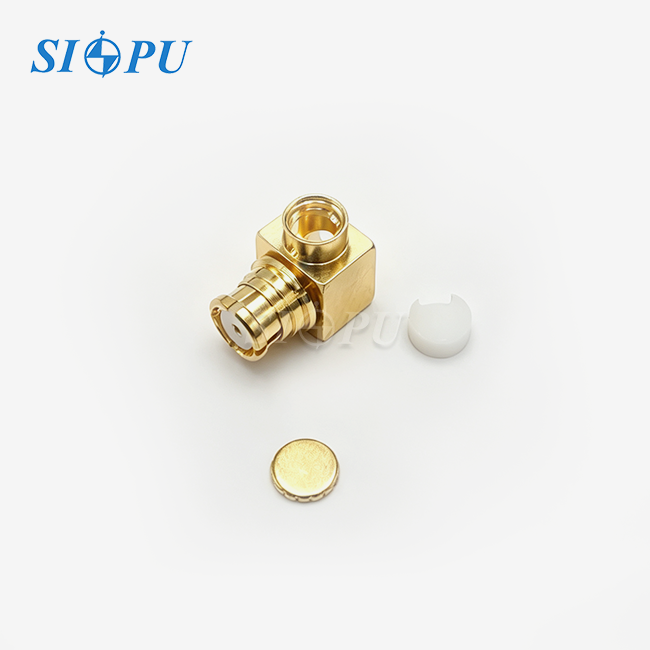
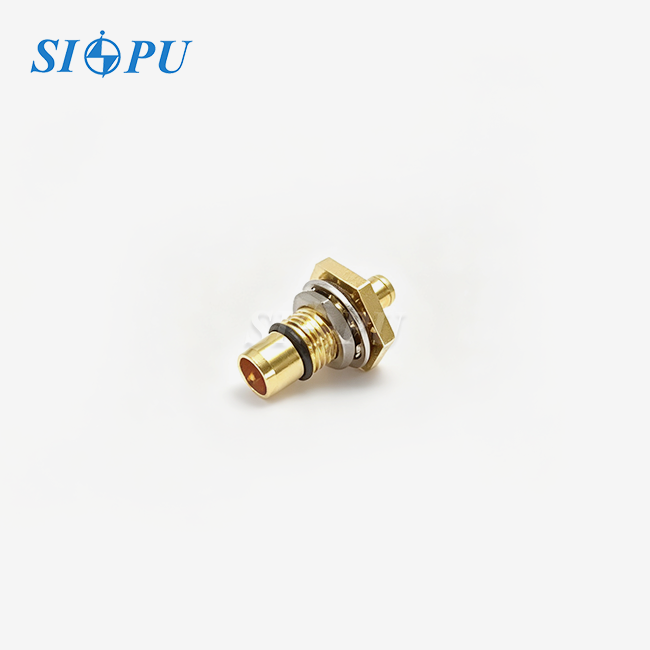
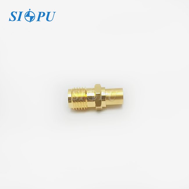
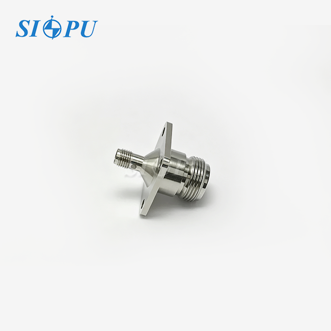
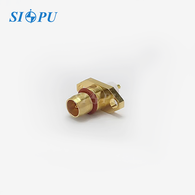
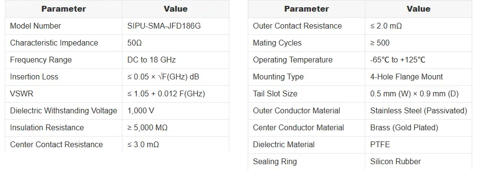
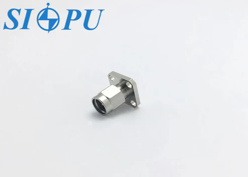
The SIPU-SMA-JFD186G has a tail with 0.5 mm wide and 0.9 mm deep slots. This center wire in the shape of a tab is directly linked to the microstrip trace. This cuts down on the length of the shift and the stray inductance. With its four holes, the stainless steel plate firmly holds the outer wire ground reference to the frame. This stops the ground path from moving around and creating resonances that aren't needed.
Why Impedance Continuity at the Launch Point Is Non-Negotiable?
To get close to 18 GHz, a wavelength in PTFE dielectric is about 10 mm. A small error in the transition of only 0.3 mm can make a big difference in the length of a wave, causing return loss degradation that can be measured. The SIPU-SMA-JFD186G has a VSWR of ≤ 1.05 + 0.012·F(GHz), which means that at 10 GHz, it has a return loss of more than 20 dB. This number shows that the microstrip launch has good control over its size.
Key Specifications and Performance Factors of the SMA Male Flange Mount Microstrip Connector 18GHz
Electrical Performance Parameters That Matter
The SMA male flange mount microstrip connector 18GHZ has a characteristic impedance of 50 Ω from DC to 18 GHz and an insertion loss of less than 0.05 × √F(GHz) dB. At 18 GHz, this method gives a result of about 0.21 dB, which is much lower than the ≤ 0.15 dB flat specification for generic SMA connections up to 18 GHz, which doesn't take into account frequency-dependent skin effect losses. Electrical separation quality is proven by insulation resistance of at least 5,000 MΩ and a dielectric voltage of 1,000 V.
Mechanical Specifications That Protect Signal Integrity
The connector can be used from -65 °C to +125 °C and has a rating of at least 500 mating cycles. Inside the contact, the resistance stays below 3.0 mΩ, and outside the contact, it stays below 2.0 mΩ. Because these values are so low, thermal noise doesn't add much, which is important in receiver front-end applications where noise figure budgets are limited.
Materials and Their Functional Role
These are the four material options and the technical reason for each one:
- Passivated stainless steel outer body: Resists oxidation in humid and salt-spray environments without requiring gold plating on the housing, keeping cost controlled while maintaining structural strength.
- Gold-plated brass center conductor: Brass provides the conductivity and machinability needed for precise pin geometry; gold plating stops oxidation from degrading contact resistance over years of field use.
- Virgin PTFE dielectric: PTFE holds a stable dielectric constant of approximately 2.1 across the full operating temperature range, preventing the impedance profile from drifting with temperature.
- Silicon rubber sealing ring: Provides environmental sealing against moisture ingress without interfering with the RF signal path.
The three most common ways that high-frequency flange connectors break are oxidation-driven contact resistance rise, dielectric dimensional instability, and mechanical fatigue at mounting points.
Practical Applications and Benefits in B2B Procurement and Engineering
Where Engineers Deploy This Connector
When it comes to 5G AAU modules, phased-array antenna feed networks, radar front-end systems, and benchtop test instruments, the SMA male flange mount microstrip connector 18GHZ fits right in. In every case, the flange mount moves the mating forces from the PCB to the chassis. This keeps fine-pitch solder joints safe in tight board layouts. This mechanical advantage lowers the number of failures in the field and the cost of warranties for OEM engineers who are making a lot of microwave subsystems.
Compatibility With Standard RF Components
The SMA male connector fits into standard SMA female plugs and can be mechanically connected to both 3.5 mm and 2.92 mm connectors. However, the system bandwidth is limited by the 18 GHz SMA specification. The SIPU-SMA-JFD186G is a good choice for combining low-noise amplifiers, filters, and switches with 3.5 mm inputs because it doesn't need an extra adapter.
Installation Best Practices for Optimal Transition Performance
Whether the required VSWR is reached in practice depends on how well the PCB is laid out at the connection footprint. Before fabrication, you should figure out that the trace width that feeds the 0.5 mm tail slot is 50 Ω on your specific substrate. It is important to properly tighten the four holes in the flange so that the outer ground plane doesn't tilt, which would change the resistance at the launch pad.
Buying Guide and Decision Support for the SMA Male Flange Mount Microstrip Connector 18GHz
Evaluating Supplier Quality Before Ordering
If you are looking for an 18 GHz flange-mount microstrip connector, make sure you ask for Vector Network Analyzer (VNA) test data that covers the whole range from DC to 18 GHz, not just a pass/fail stamp for a single frequency. SIPU checks each batch of plating using X-Ray Fluorescence (XRF) to make sure the gold is thick enough, gives salt-spray rust test results according to ASTM B117, and gives dimensional gaging reports that show pin protrusion meets MIL-STD-348 geometry limits.
Procurement Criteria That Reduce Program Risk
When buying RF connectors, there are three things that always set low-risk sellers apart from high-risk ones:
- Batch traceability: Every production lot should carry a traceable batch code linking back to raw material certifications, plating records, and VNA test results. This allows rapid isolation of any non-conforming units if a field issue emerges.
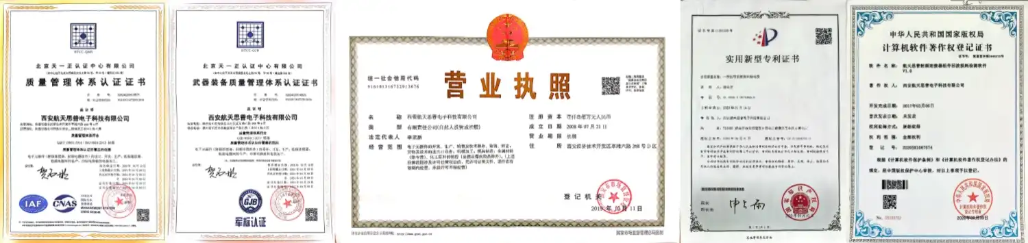
- Regulatory compliance documentation: RoHS, REACH, IEC, CE, and UL compliance certificates should be current and available on request—not just stated on a datasheet.
- Sample-to-production consistency: The sample you qualify should match production units in plating thickness, dimensional tolerance, and dielectric material grade. Request first-article inspection reports when transitioning from sample to volume order.
Checking these three things before placing a large order greatly lowers the chance of batch non-conformance, which is the main reason why OEM programs are held up when buying RF connectors.
Optimizing Performance and Future Trends in SMA Male Flange Mount Microstrip Connectors
Common Performance Challenges at High Frequencies
Most of the time, VSWR peaks that aren't expected happen in flange-mount setups because the ground path is broken. A resonant cavity forms when the chassis ground plane under the connection is broken by an over-sized clearance cutout. This means that the outer wire loses its continuous ground reference. This type of failure can be avoided by making sure the ground clearance hole stays within the specs and checking this during PCB review.
Emerging Manufacturing Approaches
SMA male flange mount microstrip connector 18GHZ Manufacturers of connectors are moving toward tighter CNC tolerances on the tail slot geometry to support substrates that are thinner than 0.5 mm. This is because phased-array and millimeter-wave modules are getting smaller. SIPU has been CNC cutting for 30 years, so the company can meet these calls for tighter tolerances without having to wait for retooling lead times, which slow down OEM projects.
Forward Compatibility With Next-Generation RF Systems
Standard SMA interfaces can handle frequencies up to 18 GHz, which is the same as current 5G sub-6 GHz and new FR2 band integration boards. These boards send data through microstrip networks before up-converting them. As system designs move toward 24–28 GHz, the microstrip transition design skills and tools made for 18 GHz connectors can be used right away on the next generation of products.
Conclusion
The microstrip transition in a flange-mount 18 GHz SMA connector is not a passive solder joint. Instead, it is a specially designed impedance structure that controls the integrity of the system signal from DC to 18 GHz. The SIPU-SMA-JFD186G solves this problem with a tail slot that is precisely measured, a passivated stainless steel housing, a gold-plated brass center contact, and a PTFE dielectric. It also comes with batch-level VNA testing and full regulatory compliance. The easiest way for OEM engineers to make sure their RF systems work well is to choose a connector that has detailed process control at every stage of production. This way, engineers won't have to worry about problems in the field or rejected batches.
FAQ
1. What is the recommended PCB trace width for the 0.5 mm tail slot?
The 0.5 mm tail slot width is a starting reference. Your actual microstrip trace width depends on substrate permittivity and thickness. Use a microstrip impedance calculator with your board material parameters to find the 50 Ω width, then taper to meet the 0.5 mm connector tail at the launch point.
2. Does the SIPU-SMA-JFD186G require a torque specification for flange screws?
SIPU recommends following MIL-STD-348 torque guidance for SMA interfaces—typically 8–10 in-lbs (0.9–1.1 Nm) for the mating interface—and applying consistent torque to all four flange mounting screws to keep the ground plane flat against the chassis.
3. Is EAR99 classification confirmed for export of this connector?
SMA connectors operating to 18 GHz typically fall under EAR99. However, 18 GHz is close to the ECCN 3A001.a threshold (5.85–31 GHz for radar and communications equipment), so each export transaction should be reviewed individually based on the end use and destination country.
4. Can the connector be re-plated or refurbished after field use?
Re-plating field-returned connectors is not recommended because the dimensional tolerances at the microstrip tail and center pin are set during initial machining. Any post-process coating operation risks altering pin diameter and degrading VSWR performance above 10 GHz.
Request Your SMA Male Flange Mount Microstrip Connector 18GHz Sample From SIPU Today
Since 1998, SIPU RF Technology has been giving top-level RF interconnect solutions to engineers in the aerospace, telecommunications, and test instrumentation industries. You can buy the SIPU-SMA-JFD186G SMA male flange mount microstrip connector 18GHZ right now. It comes fully tested and ready to go. SIPU makes direct SMA male flange mount microstrip connector 18GHZ and offers help from samples to production, competitive OEM prices, and all-in-one technical support. To get a datasheet, sample, or bulk price, email SIPU at info@sipu-rf.com or go to sipuconn.com.
References
1. Pozar, D. M. Microwave Engineering, 4th ed. Wiley, 2011.
2. IEC 61169-15:2010 — Radio-Frequency Connectors — Part 15: Sectional Specification for SMA Series Connectors. International Electrotechnical Commission, 2010.
3. MIL-STD-348B — Interface Standard: Radio Frequency Connector Interfaces for MIL-PRF-39012, MIL-PRF-55339, MIL-PRF-23329, MIL-PRF-3643, MIL-PRF-3650, and MIL-PRF-49142. U.S. Department of Defense, 2013.
4. Wadell, B. C. Transmission Line Design Handbook. Artech House, 1991.
5. ASTM B117-19 — Standard Practice for Operating Salt Spray (Fog) Apparatus. ASTM International, 2019.
6. Williams, D. F., and Marks, R. B. "Transmission Line Capacitance Measurement." IEEE Microwave and Guided Wave Letters, vol. 1, no. 9, 1991, pp. 243–245.
Contact us directly for customized solutions, quotations and long-term strategic cooperation.