- English
- French
- German
- Portuguese
- Spanish
- Russian
- Japanese
- Korean
- Arabic
- Greek
- German
- Turkish
- Italian
- Danish
- Romanian
- Indonesian
- Czech
- Afrikaans
- Swedish
- Polish
- Basque
- Catalan
- Esperanto
- Hindi
- Lao
- Albanian
- Amharic
- Armenian
- Azerbaijani
- Belarusian
- Bengali
- Bosnian
- Bulgarian
- Cebuano
- Chichewa
- Corsican
- Croatian
- Dutch
- Estonian
- Filipino
- Finnish
- Frisian
- Galician
- Georgian
- Gujarati
- Haitian
- Hausa
- Hawaiian
- Hebrew
- Hmong
- Hungarian
- Icelandic
- Igbo
- Javanese
- Kannada
- Kazakh
- Khmer
- Kurdish
- Kyrgyz
- Latin
- Latvian
- Lithuanian
- Luxembou..
- Macedonian
- Malagasy
- Malay
- Malayalam
- Maltese
- Maori
- Marathi
- Mongolian
- Burmese
- Nepali
- Norwegian
- Pashto
- Persian
- Punjabi
- Serbian
- Sesotho
- Sinhala
- Slovak
- Slovenian
- Somali
- Samoan
- Scots Gaelic
- Shona
- Sindhi
- Sundanese
- Swahili
- Tajik
- Tamil
- Telugu
- Thai
- Ukrainian
- Urdu
- Uzbek
- Vietnamese
- Welsh
- Xhosa
- Yiddish
- Yoruba
- Zulu
What is an SMA Connector? Everything You Need to Know
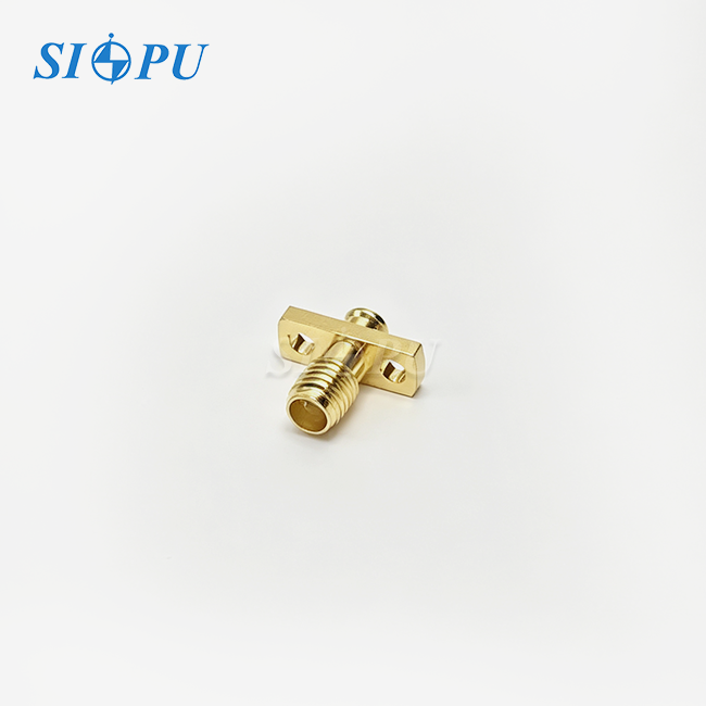
If you work in RF engineering or B2B procurement for microwave systems, you have almost certainly encountered SMA connectors. An SMA (SubMiniature version A) connector is a precision coaxial interface standardized at 50 Ω impedance, originally developed in the 1960s for military microwave applications. Today, the SMA male flange mount microstrip connector 18GHz represents the refined evolution of that legacy — engineered for direct PCB integration, chassis-level mechanical security, and reliable signal transmission from DC to 18 GHz. This article covers everything you need to know to evaluate, select, and source the right connector for your system.
Understanding SMA Connectors: Definition and Core Features
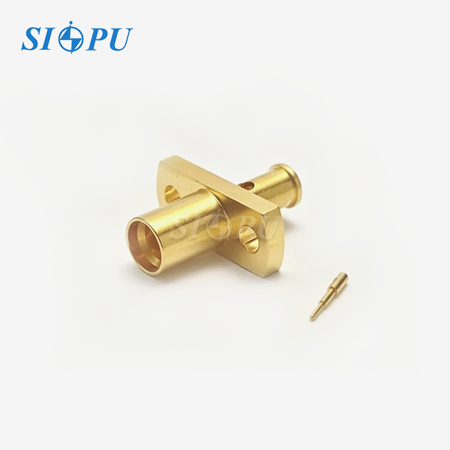
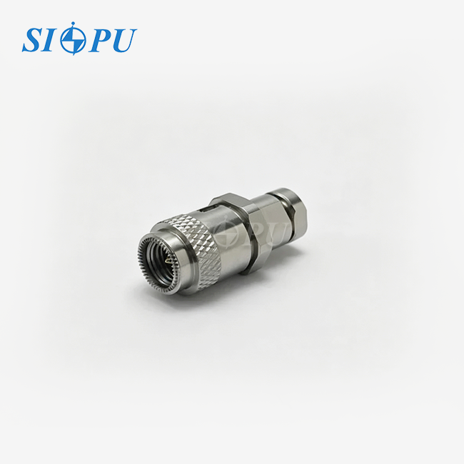
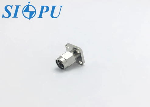
The performance of SMA connectors comes from their precise shape, carefully chosen dielectric materials, and a threaded coupling mechanism. In the male interface, there is a center pin. The flange mount version uses a four-hole bolt design to attach the body directly to the chassis wall instead of just using PCB solder pads.
Structural Elements That Matter
What engineers call the "industry standard" SMA stack is made up of a passivated stainless steel housing, a gold-plated brass center conductor, and a PTFE dielectric. Stainless steel provides corrosion resistance and helps withstand mechanical vibration. The gold plating protects the brass contact from oxidation and helps maintain contact resistance below 3.0 mΩ. PTFE has a stable dissipation factor between -65 °C and +125 °C, which is important for both outdoor communication enclosures and airborne radar units.
Key Electrical Specifications
From DC to 18 GHz, the SIPU-SMA-JFD186G has a VSWR of ≤ 1.05 + 0.012 × F(GHz) and an insertion loss of ≤ 0.05 × √F(GHz) dB. Insulation resistance is more than 5,000 MΩ, and the dielectric can withstand a voltage of 1,000 V. When RF system engineers require a high-frequency SMA connection for signal-chain applications, these specifications provide key performance parameters for evaluation.
Why the Flange Mount Design Wins
All of the mating torque from a standard edge-mount or end-launch connector goes straight to the copper pads on the PCB. The four-hole flange distributes the mechanical load across the chassis, reducing stress on the board and its solder joints. This is very important in 5G AAU modules and phased-array panels, where space on the board is limited and there are constant vibration cycles.
Applications of SMA Male Flange Mount Microstrip Connectors at 18GHz
The flange mount microstrip setup solves a specific integration problem: how do you get a coaxial signal from an outside cable or the wall of an enclosure to a microstrip transmission line with as little reflection as possible and as much mechanical stability as possible? That answer works for a lot of different tough situations.
Telecommunications and 5G Infrastructure
5G base station front-end modules work in sub-6 GHz bands and new millimeter-wave bands. Outside cables connect to the internal RF board through the SMA male flange mount microstrip connector 18GHz. This is where the cables transition to a 50 Ω microstrip trace. The 4-hole plate remains securely fixed even under wind loads and temperature fluctuations, helping prevent mechanical stress on the PCB.
Aerospace and Defense Radar Systems
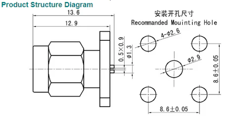
Connectors for radar sensors, electronic warfare units, and SATCOM ground connections need to be able to handle shock, extreme temperatures, and years of use in the field. Since this connector can work in temperatures ranging from -65 °C to +125 °C and has a stainless steel body, it is suitable for demanding environmental conditions. However, compliance with MIL-STD-810 must be verified through the relevant qualification testing rather than inferred from the connector's materials and temperature range alone. PCB layout engineers can use the tail slot, which is 0.5 mm wide and 0.9 mm deep, as a reference when designing the impedance-matched launch pad.
Test and Measurement Instruments
Vector network analyzers, signal generators, and spectrum analyzers need connections that are secure and can be used repeatedly. Calibration drift can be minimized through a connection designed for more than 500 mating cycles and offering low, stable VSWR. That need is met by the SIPU-SMA-JFD186G, which can be connected in portable laboratory setups without requiring a torque wrench for every connection.
Comparison and Selecting the Right SMA Connector for Your Needs
Not every type of SMA works in every situation. Knowing the variations between male and female flange mount types and between SMA and other interface types can help you avoid needless reworking cycles that cost a lot of money.
SMA Male vs. Female Flange Mount Microstrip
The male version has a center pin, while the female version has a recessed contact socket. The male flange mount connector is suitable when the mating component has a female SMA interface, such as a female cable-end connector. Conversely, the female flange mount connector is used when the mating cable or device has a male SMA center pin.
The choice depends on the interface at the opposite end of the connection, not simply on whether the connector is mounted on a chassis or PCB. Before ordering, engineers should confirm the gender of the mating interface, the center-contact configuration, and the mounting orientation to ensure proper electrical and mechanical compatibility.
SMA Microstrip vs. Coaxial Connectors at 18 GHz
Coaxial edge-launch connectors keep the full coaxial shape all the way to the edge of the PCB, which means there is a little less reflection at the transition. But they need to be precisely machined along the board edges. The microstrip tail on a flange mount connection can handle more variations in PCB manufacturing, and the signal entry point can be on the board surface anywhere, not just at the edge. That freedom is more important than a small VSWR difference for high-density RF units.
SMA vs. N-Type Above 10 GHz
In standard form, N-type connections can handle frequencies up to approximately 11 GHz, while precision versions can extend to 18 GHz. They cost more per unit and are bigger and heavier. Below 18 GHz, the SMA offers comparable electrical performance to the N-type connector in applications within their respective frequency specifications, but with a much smaller footprint. That's why the SMA male flange mount microstrip connector 18GHz is a practical choice when board space or weight is limited, like in phased-array systems and portable test equipment.
Here are the things that will help you decide which SMA flange mount choice is best for your application:
- Frequency ceiling: Confirm the supplier's VSWR specification is measured and guaranteed at 18 GHz, not just rated at a lower frequency with extrapolated data.
- Tail slot dimensions: The 0.5 mm × 0.9 mm slot must match your PCB substrate thickness and trace width for your target impedance.
- Environmental rating: Verify the sealing ring material — silicone rubber handles both low-temperature and UV exposure better than generic elastomers.
- Batch consistency: Request batch-level test data including plating thickness via XRF measurement and VNA sweep results across the full frequency range.
Before placing a sample order, these criteria give your engineering team a concrete list to follow. This lowers the chance of getting connectors that look good but fail system integration tests.
Procurement Guide: How to Source SMA Male Flange Mount Microstrip Connectors at 18GHz
It takes more than just getting the cheapest unit price to get the right connection in large quantities. When buying RF components from a business to business (B2B) supplier, you have to look at things like lead times, sample methods, batch certification, and how quickly the seller responds.
Evaluating Suppliers and Brands
Amphenol, Radiall, Pasternack, Molex, TE Connectivity, and Johnson/Cinch are all well-known brands in the SMA connector market. Each has a standard SMA geometry, but the lead time, minimum order quantity, and ability to make custom parts are different. SIPU RF Technology was established in 1998 and is based in Xi'an, China. It has 30 years of experience in direct manufacturing, is ISO 9001 certified, and follows RoHS, REACH, IEC, CE, and UL standards. Their partner in North America, JNP Supplies LLC in Seattle, Washington, helps procurement teams in the United States in a way that is specific to their needs.
Pricing and Lead Time Factors
Standard stock SMA plugs are sent out within 72 hours from SIPU's stock. Different plating choices, changed tail geometries, or military-profile paperwork packages are just a few of the custom designs that go through their own production lines with priority scheduling. Pricing is good for orders of 200 to 1,200 units, which is typical for OEMs, and pricing for mixed samples is available for engineering qualification runs.
Best Practices for the Inquiry Process
Start your inquiry by requesting a clear set of technical documents. Make sure the seller can provide XRF plating reports, physical inspection records, and batch-level VSWR sweep data from a VNA. Ask for readings at 6 GHz, 12 GHz, and 18 GHz for the SMA male flange mount microstrip connector 18GHz to make sure the VSWR formula is validated across the whole range. Ask for samples before committing to large quantities. SIPU allows sample orders to speed up the engineering approval process.
Conclusion
For more than 50 years, SMA connectors have been the standard way to connect microwave signals. This is because the basic design works well with manufacturing precision. The SMA male flange mount microstrip connector 18GHz builds on that base and adds chassis-level mechanical security, direct PCB microstrip integration, and materials that can be used in harsh environments. These specs—VSWR, insertion loss, mating cycles, temperature range, and tail slot dimensions—give you a full basis for evaluation, no matter what you're using it for: a 5G base station front end, an airborne radar detector, or a benchtop network analyzer. Compare these parameters to the needs of your system, and ask for samples early on in the planning process.
FAQ
1. What is the maximum usable frequency for an SMA connector?
Standard SMA connectors are specified to 18 GHz. Precision versions using tighter dimensional tolerances can reach 26.5 GHz, but performance above 18 GHz is not guaranteed for standard-grade parts. For applications above 18 GHz, consider 2.92 mm (K) or 2.4 mm interface connectors.
2. Why choose a flange mount over an edge-mount SMA?
Flange mounts transfer mechanical load to the chassis rather than the PCB. This protects solder joints from fatigue caused by repeated mating cycles or vibration, which is a significant reliability advantage in field-deployed equipment.
3. Can an SMA connector handle high-power RF signals?
SMA connectors are optimized for signal-level transmission. Power handling depends on frequency, VSWR, and local thermal conditions. Contact the connector manufacturer's engineering team with your specific power level, frequency, and duty cycle before selecting a part for transmit-chain use.
4. How do I verify batch quality before a production order?
Request VNA-measured VSWR data, XRF plating thickness reports, and dimensional inspection records for each production batch. A supplier with mature in-house quality systems — like ISO 9001-certified production — should provide these documents routinely.
5. Is the SIPU-SMA-JFD186G compatible with standard SMA female interfaces?
Yes. The connector follows SMA geometry consistent with MIL-STD-348, making it intermateable with standard SMA female connectors from any qualified manufacturer.
Request a Sample or Datasheet from SIPU — Your SMA Male Flange Mount Microstrip Connector 18GHz Supplier
SIPU RF Technology ships the SIPU-SMA-JFD186G straight from its factory in Xi'an. The company has been making high-quality RF connectors for 30 years. It is a confirmed manufacturer of the SMA male flange mount microstrip connector 18GHz. SIPU offers quality that is ISO 9001-certified, RoHS/REACH compliance, batch-level test documentation, and quick technical support through its partner in Seattle, USA. You can get the full information at sipuconn.com, or you can start a sample request right away by sending your specs to info@sipu-rf.com.
References
1. Pozar, D. M. Microwave Engineering, 4th ed. — Wiley, 2011.
2. IEEE Standard 287-2007: Precision Coaxial Connectors (DC to 110 GHz) — IEEE, 2007.
3. MIL-STD-348B: Interface Standard for RF Connector Interfaces for MIL-PRF-39012 Connectors — U.S. Department of Defense, 2012.
4. RF & Microwave Connector Selection Guide — Microwave Journal, 2020.
5. Hirose, A. & Lonngren, K. Introduction to Wave Phenomena — Wiley, 2010.
6. IEC 61169-15: Radio-frequency Connectors — Part 15: Sectional Specification for SMA Connectors — International Electrotechnical Commission, 2013.
Contact us directly for customized solutions, quotations and long-term strategic cooperation.