- English
- French
- German
- Portuguese
- Spanish
- Russian
- Japanese
- Korean
- Arabic
- Greek
- German
- Turkish
- Italian
- Danish
- Romanian
- Indonesian
- Czech
- Afrikaans
- Swedish
- Polish
- Basque
- Catalan
- Esperanto
- Hindi
- Lao
- Albanian
- Amharic
- Armenian
- Azerbaijani
- Belarusian
- Bengali
- Bosnian
- Bulgarian
- Cebuano
- Chichewa
- Corsican
- Croatian
- Dutch
- Estonian
- Filipino
- Finnish
- Frisian
- Galician
- Georgian
- Gujarati
- Haitian
- Hausa
- Hawaiian
- Hebrew
- Hmong
- Hungarian
- Icelandic
- Igbo
- Javanese
- Kannada
- Kazakh
- Khmer
- Kurdish
- Kyrgyz
- Latin
- Latvian
- Lithuanian
- Luxembou..
- Macedonian
- Malagasy
- Malay
- Malayalam
- Maltese
- Maori
- Marathi
- Mongolian
- Burmese
- Nepali
- Norwegian
- Pashto
- Persian
- Punjabi
- Serbian
- Sesotho
- Sinhala
- Slovak
- Slovenian
- Somali
- Samoan
- Scots Gaelic
- Shona
- Sindhi
- Sundanese
- Swahili
- Tajik
- Tamil
- Telugu
- Thai
- Ukrainian
- Urdu
- Uzbek
- Vietnamese
- Welsh
- Xhosa
- Yiddish
- Yoruba
- Zulu
How SMA Male Flange Mount Microstrip Connector 18GHZ Fits High-Density RF Modules
When RF engineers ask how a single connector can make or break a high-density module design, the answer often points to mounting geometry and signal integrity at the board-level transition. The SMA male flange mount microstrip connector 18GHz solves both problems at once. By anchoring directly to the chassis wall through a 4-hole flange and transitioning to the PCB via a precision microstrip tail, it delivers DC-to-18GHz signal continuity, VSWR ≤ 1.05 + 0.012F(GHz), and insertion loss ≤ 0.05 × √F(GHz) dB—all inside a footprint compact enough for today's tightly packed RF assemblies.
Understanding the SMA Male Flange Mount Microstrip Connector 18GHz
Core Construction and Interface
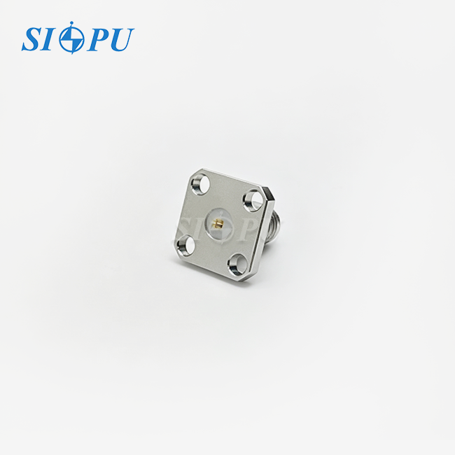
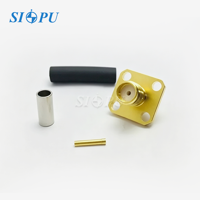
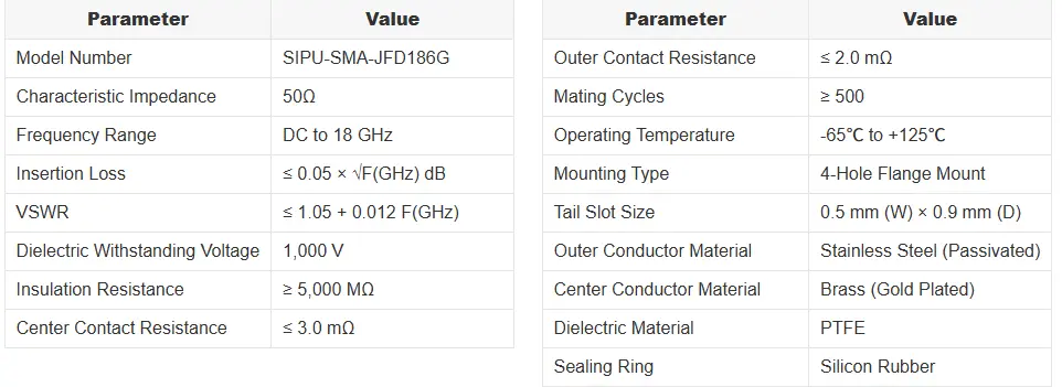
The SIPU-SMA-JFD186G has a body made of passivated stainless steel, a center conductor made of gold-plated brass, and a dielectric made of PTFE. The connection is held in place by a 4-hole lip, and a 0.5 mm × 0.9 mm slotted microstrip tail connects straight to a 50Ω PCB trace. The standard for SMA connectors that are meant to work at microwave frequencies is this mix of three materials: stainless steel, brass, and PTFE.
Key Electrical Specifications
At a characteristic impedance of 50Ω, the connector keeps the center contact resistance below 3.0 mΩ and the insulation resistance above 5,000 MΩ. The dielectric can handle up to 1,000 V of voltage, and the connector is rated for at least 500 mating cycles in temperatures ranging from -65°C to +125°C. These pictures are in line with what MIL-STD-348 says about the shape of SMA connections.
Where These Connectors Are Used
There are 5G AAU panels, phased-array radar front-ends, satellite communication modules, and bench-top test instruments that use the SMA male flange mount microstrip connector 18GHZ. Each use needs a connection that keeps its electrical properties even after joining multiple times and going through thermal cycling. This design meets all of those needs.
Technical Insights and Design Considerations for 18GHz SMA Flange Mount Connectors
Signal Integrity at the PCB Transition
The most important part of this connector's performance is the microstrip tail geometry. Its width of 0.5 mm is the same as a normal 50Ω microstrip on Rogers 4350B at typical substrate thicknesses. This lowers the impedance discontinuity that causes return loss. IPC-2141A says that changing the shape of the trace at RF launch points has a direct effect on system return loss budgets.
Electromagnetic Isolation in Dense Layouts
Multiple signal lines are packed into high-density RF units so that they are only millimeters apart. The body of the stainless steel flange acts as a ground fence around the transition from coaxial to microstrip, stopping channels from cross-coupling with each other. When channel-to-channel separation is important, RF system engineers choose flange-mount designs over vertical PCB-mount options because of this blocking effect.
Thermal and Mechanical Stability
PTFE's dielectric constant stays the same (about 2.1) from -65°C to +125°C. This, along with the silicon rubber sealing ring, stops impedance drift during temperature cycling, which is a common way for outdoor telecom enclosures and aerospace pods to fail. The flange mount transfers the torque of the connector to the chassis instead of the PCB. This protects the solder joints over the life of the product.
Comparing SMA Male Flange Mount Connectors with Alternative Connectors at 18GHz
At 18GHz, the frequency limit, module density, and mechanical load needs must be taken into account when choosing the right connection type. This is how the main choices stack up:
- N-Type connectors handle frequencies up to 11 GHz in standard versions and up to 18 GHz in precision variants, but their larger body diameter (roughly 16 mm across the hex) consumes panel real estate that high-density modules cannot spare. N-Type suits high-power outdoor antenna ports rather than board-level integration.
- SMP (GPO) snap-on connectors excel in blind-mate applications and offer a very small footprint, but their upper frequency limit of 40 GHz comes with a lower power rating and a mating cycle life of approximately 100–500 cycles depending on the interface class—comparable to SMA but with less panel-mount rigidity.
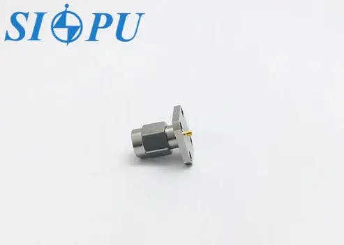
- SMA male flange mount microstrip connector 18GHz occupies the middle ground: a body small enough for dense layouts (hex across flats ~7.9 mm), a 4-hole flange that transfers mating forces to the chassis, and verified performance to 18 GHz with low insertion loss. For OEM engineers sourcing components for phased-array modules or microwave subsystems, this profile generally offers the best balance of frequency range, mechanical security, and procurement availability.
The best choice depends on your layout, but the SMA flange mount design is still the most popular choice for DC-to-18GHz board-level RF input/output ports that are mounted on a chassis.
Procurement and Sourcing Strategies for SMA Male Flange Mount Microstrip Connector 18GHz
Verify Batch Consistency Before Committing to Volume
RF engineers who have run OEM supply chains know that a connection that works well in a sample may not work as well in mass production if the plating thickness or dielectric concentricity changes from batch to batch. For each production lot, ask for VSWR data measured by VNA and XRF plating thickness reports. SIPU RF Technology gives you inspection records for each batch that include gold plating adhesion, dimensional gaging, and dielectric withstanding voltage testing. You can use these records to compare the goods to your acceptance criteria before they are shipped.
Understand Lead Time and Inventory Position
You can get standard SMA male flange mount microstrip connector 18GHZ units from stock and have them delivered in 72 hours. Custom variants, like tails with non-standard sizes or different plating requirements, are made on separate production lines that get priority scheduling. When buying from an OEM that takes one to three months, timing your engineering trial phase with their standard stock program lowers the risk of missing a deadline and doesn't raise the cost per unit.
Compliance and Export Classification
These plugs meet the requirements of RoHS, REACH, IEC, CE, and UL. When exported to the US, SMA plugs at 18GHz are usually labeled EAR99. However, 18GHz is close to the ECCN 3A001.a cutoff, which covers radar and communications gear in the 5.85–31GHz range. We suggest that you check the rating with your trade compliance team for each sale.
How SMA Male Flange Mount Microstrip Connectors Enhance High-Density RF Modules: Use Cases and Future Outlook
5G Active Antenna Units
In 5G AAU designs, there needs to be a reliable RF port between the antenna array panel and the beamforming PCB for each antenna element column. The SMA male flange mount microstrip connector 18GHZ offers a smooth, low-loss transfer at sub-6GHz and FR1 frequencies. The flange mount also protects against vibrations that might happen during outdoor installations. People who work in production say that chassis-anchored flange connectors lower field return rates in high-vibration tower-top deployments compared to board-edge options.
Phased-Array Radar Front-Ends
Phased-array radar devices need the VSWR to be the same on all T/R channels. Even a VSWR difference of 0.05 between connectors can cause an amplitude taper that can be measured across the aperture. When radar system designers choose connectors from the same production lot and test them with a VNA to make sure the VSWR is ≤ 1.05 + 0.012F(GHz) across DC to 18GHz, their calibration methods can find channels that are all the same.
Future Integration Trends
The need for small, board-interfacing connectors with proven microwave performance will increase as RF packaging goes toward higher integration rates and wider bandwidth. The 4-hole flange mount style, which is the same for all MIL-STD-348-compliant interfaces, makes sure that modules made today will still work with next-generation container designs. SIPU's plans for manufacturing include wider frequency coverage and stricter VSWR requirements to meet the changing needs of millimeter-wave and phased-array systems.
Conclusion
The SMA male flange mount microstrip connector 18GHZ solves three problems that keep coming up in the design of high-density RF modules: it is stable under mating loads, the VSWR stays the same across production runs, and it has a small shape that fits dense board layouts. It has a passivated stainless steel body made for harsh settings and batch-level quality paperwork that supports OEM acceptance testing. The SIPU-SMA-JFD186G has been tested for electrical performance from DC to 18GHz. Having stock on hand, compliance paperwork, and the ability to track production within the company all lowers sourcing risk at both the sample and volume levels for procurement teams that have to work with short qualification cycles.
FAQ
1. What is the difference between an SMA male flange mount and a standard SMA edge-mount connector?
A flange mount anchors to the chassis through four bolts, transferring mating torque away from the PCB. An edge-mount connector relies on solder joints to bear all mechanical loads. In vibration-prone or frequently mated applications, the flange mount significantly extends solder joint life.
2. Can the microstrip tail accommodate different PCB thicknesses?
The tail slot (0.5 mm W × 0.9 mm D) is optimized for standard 50Ω microstrip trace widths on common RF substrates. For non-standard board thicknesses or unusual dielectric materials, contact SIPU's engineering team to evaluate trace geometry and impedance match.
3. Is this connector compatible with 3.5mm or 2.92mm interfaces?
Yes. The SMA interface is mechanically compatible with 3.5mm and 2.92mm (K) connectors. System bandwidth will be limited to the SMA's 18GHz ceiling.
4. How many mating cycles can I expect in production?
The SIPU-SMA-JFD186G is rated for ≥ 500 mating cycles. For test fixture applications with higher cycle counts, discuss contact material options with our team.
5. What torque should I apply during mating?
Use a calibrated torque wrench set to 8–10 in-lbs (0.9–1.1 Nm). Over-tightening deforms the center pin; under-tightening introduces intermittent contact resistance.
Request a Sample or Quote — Contact SIPU RF Technology Today
Since 1998, SIPU RF Technology has been making high-precision RF connectors. The SMA male flange mount microstrip connector 18GHZ is the result of more than 25 years of experience in application engineering. SIPU is a verified SMA male flange mount microstrip connector 18GHZ supplier that has stock on hand and dedicated OEM production lines. They can help you with all parts of the procurement process, from the datasheet to mass production. You can get a sample, technical datasheet, or production quote by going to sipuconn.com or emailing info@sipu-rf.com.
References
1. IPC-2141A, Controlled Impedance Circuit Boards and High Speed Logic Design, IPC, 2004.
2. MIL-STD-348B, Radio Frequency Connector Interfaces for MIL-PRF-39012 Connectors, U.S. Department of Defense, 2010.
3. MIL-PRF-39012G, Connectors, Coaxial, Radio Frequency, General Specification For, U.S. Department of Defense, 2013.
4. IEEE Microwave Magazine, "Connector and Transition Design for Millimeter-Wave Phased Arrays," IEEE, 2021.
5. ASTM B117, Standard Practice for Operating Salt Spray (Fog) Apparatus, ASTM International, 2019.
6. Microwave Journal, "SMA Connector Performance Characterization from DC to 18 GHz," Horizon House Publications, 2020.
Contact us directly for customized solutions, quotations and long-term strategic cooperation.