- English
- French
- German
- Portuguese
- Spanish
- Russian
- Japanese
- Korean
- Arabic
- Greek
- German
- Turkish
- Italian
- Danish
- Romanian
- Indonesian
- Czech
- Afrikaans
- Swedish
- Polish
- Basque
- Catalan
- Esperanto
- Hindi
- Lao
- Albanian
- Amharic
- Armenian
- Azerbaijani
- Belarusian
- Bengali
- Bosnian
- Bulgarian
- Cebuano
- Chichewa
- Corsican
- Croatian
- Dutch
- Estonian
- Filipino
- Finnish
- Frisian
- Galician
- Georgian
- Gujarati
- Haitian
- Hausa
- Hawaiian
- Hebrew
- Hmong
- Hungarian
- Icelandic
- Igbo
- Javanese
- Kannada
- Kazakh
- Khmer
- Kurdish
- Kyrgyz
- Latin
- Latvian
- Lithuanian
- Luxembou..
- Macedonian
- Malagasy
- Malay
- Malayalam
- Maltese
- Maori
- Marathi
- Mongolian
- Burmese
- Nepali
- Norwegian
- Pashto
- Persian
- Punjabi
- Serbian
- Sesotho
- Sinhala
- Slovak
- Slovenian
- Somali
- Samoan
- Scots Gaelic
- Shona
- Sindhi
- Sundanese
- Swahili
- Tajik
- Tamil
- Telugu
- Thai
- Ukrainian
- Urdu
- Uzbek
- Vietnamese
- Welsh
- Xhosa
- Yiddish
- Yoruba
- Zulu
How 2.92mm Male to 2.4mm Female Gold-Plated Adapter Works
A 2.92mm male to 2.4mm female gold-plated adapter works by joining a 2.92mm (K-type) male plug to a 2.4mm female socket through a short 50 Ω coaxial path. The brass body, beryllium bronze center contact, and PEI dielectric hold the line geometry steady. The signal crosses between the two interface families with low reflection. Gold plating protects the contacts from oxidation and keeps contact resistance stable over repeated mating. SIPU's model SIPU-2.92/2.4-JK covers DC-40GHz, so you can connect 2.92mm instruments to 2.4mm devices under test without altering the signal.
Why Use a 2.92mm Male to 2.4mm Female RF Adapter?
The Interface Mismatch This Adapter Solves
Most of the time, more than one company sells millimeter-wave chairs. There may be 2.92mm test ports on a network analyzer, but the device being tested has a 2.4mm connector that can handle 50 GHz. So they can't connect directly because the outer conductor inner diameters of the two interfaces are different. Making them work together hurts both of them. I think of the 2.92mm male to 2.4mm female gold-plated adapter as the planned precise link that will connect them. In a small package, it has both a mechanical match and a controlled 50 Ω electrical path. If you don't have it, every sweep has more connection changes, extra connectors, and doubt.
Where Engineers Use It
This part works with instruments and gadgets that use different types of connectors. Vector network analyzer measurements, 5G and 6G millimeter-wave characterization, radar and satellite modules, aerospace test stations, and semiconductor test setups are all common uses. A lab with a 2.92mm analyzer doesn't need to buy a second set of cables to measure 2.4mm parts. The 500+ mating cycle rating is good for production stations, and the straight, small body is good for dense routing. A 2.92mm male to 2.4mm female gold-plated adapter can work from DC to 40 GHz, even if the 2.4mm device itself can go higher. This is because the 2.92mm side sets the upper limit.
What It Replaces in the Signal Path
First, I look at other ways to connect two different types of connectors. Then I choose an adapter. Adding two wire systems with different ends gives you more length, more flexibility when you bend them, and a second way to connect. Every time a stack of general adapters meets, one reflection is added. The path is cut short by a single rigid transition that keeps the phase constant and fits snugly between a test port and a module. This adapter from SIPU is made to be very resistant to vibration, so the joint will stay in place on chairs and fixings that move or hum. This helps keep the level of your measurements steady.
How the 2.92mm Male to 2.4mm Female Adapter Works
Mechanical Structure of the 2.92mm Male to 2.4mm Female Gold-Plated Adapter
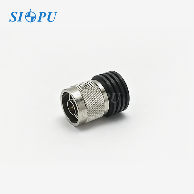
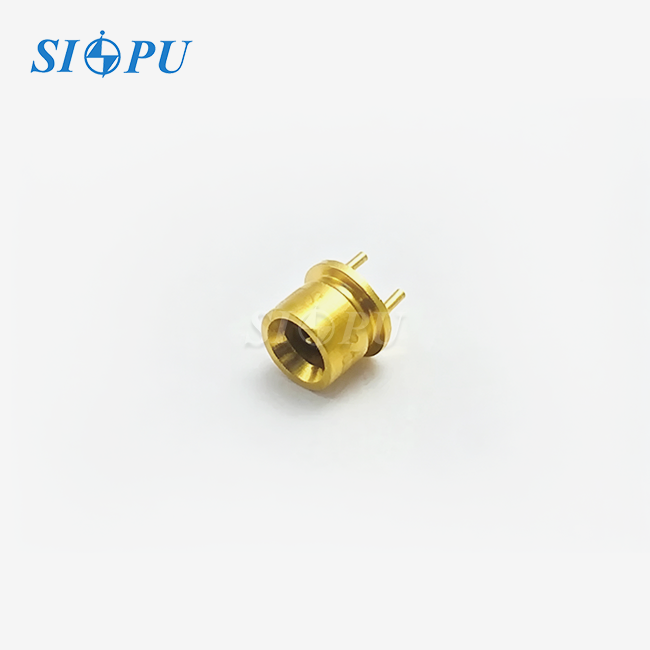
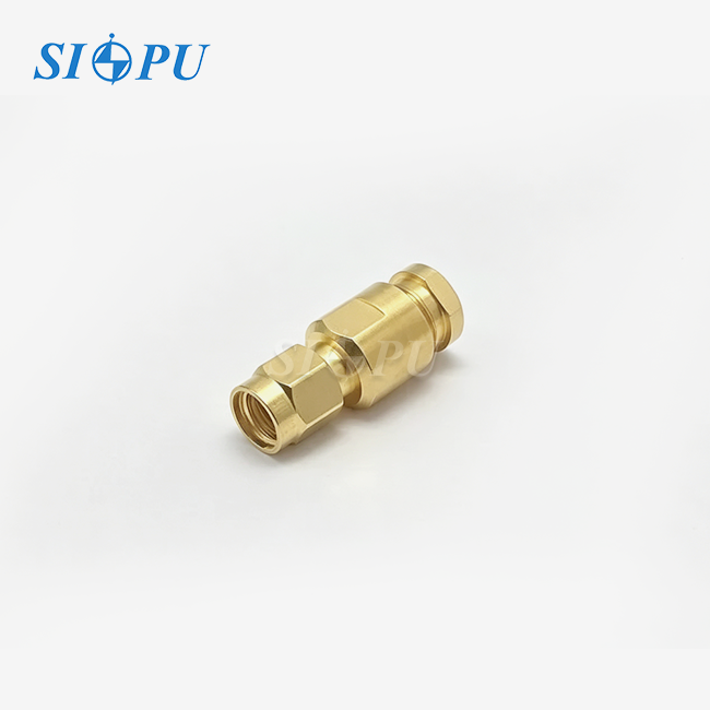
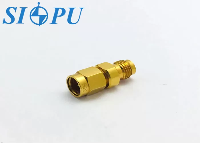
There are four main parts to the adapter: a body on the outside, a contact in the middle, a dielectric support, and a sealing ring. A male center pin and coupling nut fit with a female 2.92mm port on the 2.92mm end. A 2.4mm male plug can be plugged into a female socket on the 2.4mm end. Brass is used to make the gold-plated outer circuit, and beryllium bronze is used to make the gold-plated inner contact. The middle contact is held in place by a PEI insulator, and the joint is sealed by a silicone rubber ring. Because it is straight, both ports stay on the same line, which saves space on the bench.
Electrical Path and 50 Ω Impedance
The adapter works like a short piece of coaxial transmission line electrically. Characteristic impedance is based on the dielectric constant between the two conductors and the ratio of the inner diameter of the outer conductor to the outer diameter of the center conductor. Through the transition, the designer changes the geometry so that the line stays at 50 Ω as it goes from 2.92 mm to 2.4 mm. The part doesn't change the signal, decode it, or boost it. It only holds it. VSWR is the first number I look at because any mismatch shows up as reflected energy.
Role of Gold Plating and Beryllium Bronze Contacts
Gold doesn't oxidize, so contact surfaces don't build a film but keep a steady resistance. SIPU says that the center contact resistance should be at least 4.0 mΩ and the outer contact resistance should be at least 2.5 mΩ in this 2.92mm male to 2.4mm female gold-plated adapter. Beryllium bronze gives the middle contact spring its force, and it can keep that force even after hundreds of mating rounds. The PEI insulator and silicone rubber seal work well in temperatures between -65°F and +125°F. Gold is helpful, but it can't take the place of careful cutting. Both the shape of the part and the amount of the plating determine how long it stays correct.
Key Specifications of a 2.92mm Male to 2.4mm Female Gold-Plated Adapter
Core Specifications at a Glance
These are the numbers that have been made public for this 2.92mm male to 2.4mm female gold-plated adapter, type SIPU-2.92/2.4-JK. I'm listing them all together so that your engineers can compare them to a datasheet:
| Parameter | Value |
|---|---|
| Interface | 2.92mm male to 2.4mm female |
| Impedance | 50 Ω |
| Frequency range | DC-40GHz |
| VSWR | ≒1.05 + 0.008F(GHz) |
| Insertion loss | ≒0.05√F(GHz) dB |
| Contact resistance | ≒4.0 mΩ center, ≒2.5 mΩ outer |
| Withstanding voltage/insulation | 500 V / ≥5,000 MΩ |
| Mating cycles | ≥500 |
| Temperature | -65°C to +125°F |
| Materials | Gold-plated brass and beryllium bronze, PEI, silicone rubber seal |
The sheet doesn't say how much power it can handle, so for high-power setups, check that number with SIPU.
Reading the VSWR and Insertion Loss Formulas
If you only look at one number, it doesn't tell you much. It says that the VSWR can't be more than 1.13 at 10 GHz, 1.21 at 20 GHz, and 1.37 at 40 GHz. The return loss at those levels is about 24.3 dB, 20.4 dB, and 16.1 dB. It can only lose about 0.16 dB at 10 GHz, 0.22 dB at 20 GHz, and 0.32 dB at 40 GHz. This is a specification ceiling, not a normal reading. If you only test one point, you might miss a resonance near the top edge. Make sure you check your own sweep across the whole band.
Documentation Worth Requesting
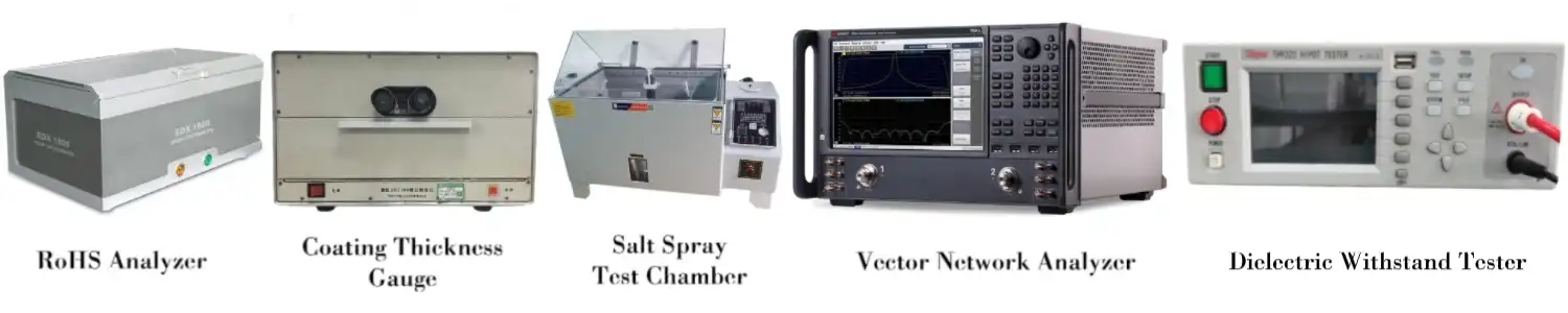
There is a step where parts are approved on paper before they are approved on the bench. You should ask for the datasheet, a dimensional drawing, information about the material and plating, and records of the inspections. SIPU checks each unit for insulation resistance and dielectric withstanding voltage. They also check the gold thickness and adhesive for each batch and make sure that every production batch meets RoHS requirements. Its design controls VSWR and insertion loss without checking those two numbers on their own. Tell SIPU technical support right away if your lab needs measured curves or records that can be tracked back to the source. This way, they can make sure that the paperwork fits your qualification process.
2.92mm Male to 2.4mm Female Adapter Compatibility and Alternatives
Matching Interfaces Correctly
To be compatible, there must be both a mechanical and an electrical match. It's important to check the gender on each side of a 2.92mm male to 2.4mm female gold-plated adapter, as well as the interface standard, the 50 Ω impedance, and the frequency rating of each link in the chain. IEC 61169-40 says that the 2.4mm interface should be used, and the 2.92mm interface is the standard K-type connection. The usable span is set by the weakest part. A 2.4 mm device can go up to 50 GHz, but a 2.92 mm port can only handle 40 GHz. If you want to know how to measure force and other things, read your instrument's instructions first.
SMA and 3.5mm Mating Limits
The 2.92mm plug can physically connect to both SMA and 3.5mm connectors, but that doesn't mean they are the same. When it comes to millimeter-wave bands, SMA links don't work as well because they were made for lower frequencies. When you have a mixed pair, you also take the maximum of the lower-rated part. I don't think SMA parts are good for precise work at 40 GHz. To work, the 2.4mm side of this adapter needs a real 2.4mm partner because 2.4mm doesn't work with SMA. Call for a different adapter set-up if you need a SMA link.
Gold-Plated Adapter vs. Cables and Other Finishes
A rigid adapter has the shortest path and a phase that stays the same. When instruments move, a cable assembly lets them do so. If the ports are close to each other, choose the adapter. If they are not, choose the cable. Gold doesn't oxidize as easily on bare or nickel-plated finishes, and it keeps contact resistance more stable. However, plating does not decide quality on its own. Like the number on the datasheet, internal geometry, machining quality, and measured RF data are all very important to me. I look at all three before I believe a number on the datasheet.
Selecting, Handling, and Verifying Your Adapter
How to Select the Best Adapter and Supplier
Start with your environment and operating band. Put VSWR, insertion loss, phase stability, and mating life in order of importance. Next, look over temperature, vibration, and clearance. Next, look at the business details, such as offering samples, the minimum order quantity (MOQ), price for large orders, customization, wait time, packaging, payment terms, and expert support. SIPU was established in 1998 in Xi'an. It has a quality system that is ISO 9001 approved and meets CE and RoHS standards. It can be used for both small-scale production and prototype testing. For projects in North America, its partner JNP Supplies LLC in Seattle, Washington, handles communication and local support in the US and Canada.
Installation and Handling Practices
Before each connection, look at both interfaces more closely. Check for dirt, threads that are bent, worn contact surfaces, and a center conductor that isn't lined up right. Just turn the connection nut and make sure the parts are lined up straight. Many instrument makers say that the torque value for 2.92mm and 2.4mm connectors should be 8 in-lb (0.90 N·m). Check your manual and use a torque wrench that has been properly calibrated. Cross-threading and tightening through a cable can change the shape of the interface and make VSWR go up. Protective caps should be kept on idle ports, parts should be kept clean and dry, joining cycles should be limited, and the adapter should be added to your plan for calibration.
Performance Verification and Common Problems
Check before you buy a lot of something. Use a calibrated VNA to sweep VSWR or return loss across the whole band you want to test. Then, use the right cables to measure insertion loss and do multiple mating tests to check for drift. Check the pin level and thread quality in terms of their sizes. If you can, calibrate at the 2.4mm plane after the adapter, or use a method that involves taking the adapter off to describe it. Some common mistakes are believing a label without checking the measurements, thinking that gold is proof of RF quality, buying without a datasheet, and tightening too much. Check a sample against your own rules, and then give the go-ahead for a batch.
Buying Checklist for a 2.92mm Male to 2.4mm Female Gold-Plated Adapter
Here is the checklist I use before giving permission.
- Technical review: First, do a technical review. Make sure you understand the 2.92mm male and 2.4mm female connectors, the 50 Ω impedance, the DC–40GHz range, the VSWR and insertion loss limits, the plating and material details, the dimension drawing, and the temperature rating. Make sure that the range works with all of your ports, and ask for power data if your setup needs it.
- Supplier review: Review the supplier and make sure you check the documentation, sample support, quality control steps, customization options, stock status, lead time, and pricing for large orders. Find out how the provider makes sure that consistency between batches is maintained. If they don't, mixed batches can change your measurement standard and require a new comparison test.
- Application review: Review of the application: Check the compatibility of the equipment, the mating torque, the need for calibration, the best way to store it, and how often it should be replaced. Write down the number of matings in your maintenance log so that you can get rid of the adapter before it starts to affect your measurements.
This list helps with engineering approval, comparing purchases, and inspecting new items.
Conclusion
Two precision coaxial interfaces are joined by a 2.92mm male to 2.4mm female gold-plated adapter. The adapter holds a 50 Ω path, and the 2.92mm side limits the pair to DC-40GHz. As the frequency goes up, so does its VSWR and insertion loss. At 40 GHz, they reach 1.37 and about 0.32 dB, respectively. This means that a full-band sweep tells you more than a single point. Gold-plated brass and beryllium bronze contacts, a PEI dielectric, and a silicone rubber seal keep the contact resistance stable for more than 500 mating cycles. However, the accuracy of the machining is just as important. They can't connect directly to each other, and SMA parts aren't accurate enough. It is important to check the adapter and instrument ports carefully, use the right pressure, and make sure the samples are correct.
FAQ
1. Can I connect 2.92mm and 2.4mm connectors straight on?
Not at all. They are from different families of interfaces and have different sizes. If you force the plugs together, you could damage the contacts and threads on both sides. Instead, use an adapter that was made just for that reason.
2. Could a SMA connection be used instead of this?
Not at all. A 2.92mm connector fits perfectly with a SMA plug, but a 2.4mm port does not. For precise millimeter-wave work, SMA parts also tend to be less repeatable.
3. What frequency range should I expect?
The 2.92mm side of this type sets the range for DC to 40GHz. Use your own sweep to check performance across the whole band, not just at one frequency.
4. When I ask for a price, what should I send?
Send the type of connector, frequency range, VSWR and insertion loss goals, quantity, delivery location, and any changes that need to be made. With these facts, SIPU can quickly suggest a good choice.
Request a Datasheet, Sample, or Quotation for a 2.92mm Male to 2.4mm Female Gold-Plated Adapter
Are you ready to find a 2.92mm male to 2.4mm female gold-plated adapter source that meets your needs? SIPU RF Technology offers prototype samples, mass production, and expert help for the SIPU-2.92/2.4-JK model. Questions are handled within 12 hours. Send an email to info@sipu-rf.com with the frequency range, quantity, and delivery location you need, or go to sipuconn.com for more information.
References
1. Pozar, D. M., Microwave Engineering, 4th Edition, 2011.
2. IEEE Std 287, IEEE Standard for Precision Coaxial Connectors (DC to 110 GHz), 2007.
3. IEC 61169-1, Radio-frequency connectors – Part 1: Generic specification, 2013.
4. Keysight Technologies, Understanding the Fundamental Principles of Vector Network Analysis, Application Note 1287-1, 2017.
5. European Parliament and Council, Directive 2011/65/EU (RoHS), 2011.
6. Collin, R. E., Foundations for Microwave Engineering, 2nd Edition, 2001.
Contact us directly for customized solutions, quotations and long-term strategic cooperation.