- English
- French
- German
- Portuguese
- Spanish
- Russian
- Japanese
- Korean
- Arabic
- Greek
- German
- Turkish
- Italian
- Danish
- Romanian
- Indonesian
- Czech
- Afrikaans
- Swedish
- Polish
- Basque
- Catalan
- Esperanto
- Hindi
- Lao
- Albanian
- Amharic
- Armenian
- Azerbaijani
- Belarusian
- Bengali
- Bosnian
- Bulgarian
- Cebuano
- Chichewa
- Corsican
- Croatian
- Dutch
- Estonian
- Filipino
- Finnish
- Frisian
- Galician
- Georgian
- Gujarati
- Haitian
- Hausa
- Hawaiian
- Hebrew
- Hmong
- Hungarian
- Icelandic
- Igbo
- Javanese
- Kannada
- Kazakh
- Khmer
- Kurdish
- Kyrgyz
- Latin
- Latvian
- Lithuanian
- Luxembou..
- Macedonian
- Malagasy
- Malay
- Malayalam
- Maltese
- Maori
- Marathi
- Mongolian
- Burmese
- Nepali
- Norwegian
- Pashto
- Persian
- Punjabi
- Serbian
- Sesotho
- Sinhala
- Slovak
- Slovenian
- Somali
- Samoan
- Scots Gaelic
- Shona
- Sindhi
- Sundanese
- Swahili
- Tajik
- Tamil
- Telugu
- Thai
- Ukrainian
- Urdu
- Uzbek
- Vietnamese
- Welsh
- Xhosa
- Yiddish
- Yoruba
- Zulu
Can SSMA Male Cable Assembly for RF Cable Maintain Phase Stability?
An SSMA male cable assembly for RF cable can hold phase steady when the connector, cable, termination, and test process fit the application. Phase stays consistent when the line keeps a 50 Ω impedance, the cable length stays within a tight tolerance, the termination is clean, and the routing respects the bend limits. SIPU's SSMA male cable assembly for RF cable covers DC–20 GHz with phase equalization of ≤±5°, insertion loss consistency of ≤±0.2 dB, and VSWR of ≤1.4. This guide explains why those figures hold, what can break them, and how you can verify them before you order.
Introduction: Why Phase Stability Matters in SSMA Male RF Cable Assemblies
Why Phase Matters in Arrays, Ground Stations, and Test Benches?
In an electronic warfare (EW) or phased array device, the phase of each channel determines where the beam goes. Fixed differences between channels can be taken away by calibrating, but only if the feed lines stay the same afterward. If you get a new cable that is a few degrees different, you may need to do a new calibration. The "Phased Array Antenna Handbook" by Mailloux talks about how random phase errors make sidelobes bigger and systematic errors move the beam. A problem that both telemetry ground stations and microwave test benches have is that a cable that isn't stable can cause measurement errors or raise questions about the link budget. Now you understand why I think of phase as a purchase specification and not a footnote.
What Is an SSMA Male Cable Assembly for RF Cable?
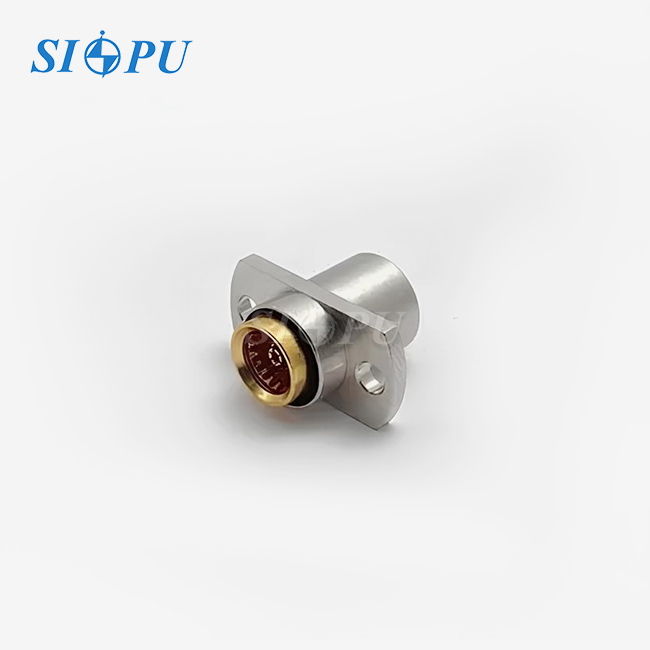
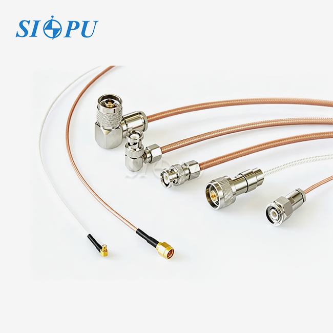
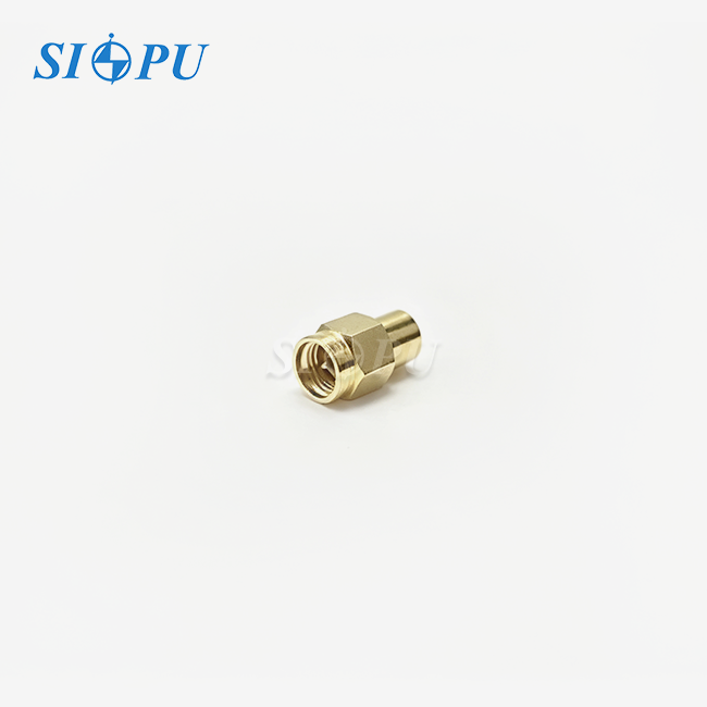
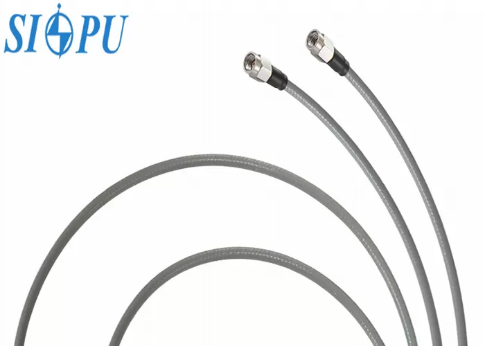
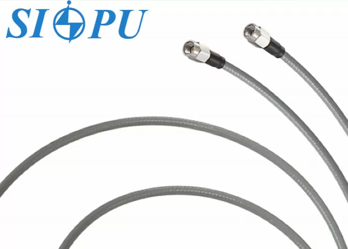
A completed interconnection is an SSMA male cable assembly for RF cable. An SSMA male connector with a small thread, a length of coaxial cable, a termination that connects them, and strain relief at the joint make it up. The signal is sent along the center conductor, its spacing is kept by the dielectric, and the field is contained by the shield. SSMA is better for crowded plans because it is smaller than SMA. A loose connector doesn't tell you much about phase because the result depends on how the cable is built and how well it is terminated. As a single unit, SIPU builds and tests the integrated assembly, so it comes ready to be put together.
How Phase Changes in Service?
What affects the electrical phase? It depends on the length, the frequency, and the dielectric. Let's say that the PTFE insulator has a velocity factor close to 0.7. Then, at 20 GHz, an extra millimeter of length adds about 35° of phase. Because of this, a ±5° limit means controlling the length by about ±0.15 mm. Temperature changes the size and dielectric constant of the wire. Bending changes its shape, vibrations can move connections, and repeated joining wears out contacts. Each effect isn't very strong by itself, but they all add up. In any SSMA male cable assembly for RF cable, these numbers demonstrate why length tolerance and termination uniformity are so important. The basic phase-constant relationship is explained in Pozar's book Microwave Engineering.
How Can an SSMA Male Cable Assembly for RF Cable Maintain Phase Stability?
Controlled Impedance and Stable Cable Construction
A constant 50 Ω impedance stops reflections, and reflections make the signal less stable and add ripple and phase uncertainty. Phase then acts based on the type of cable used. On fixed routes, semi-rigid cable keeps its shape and gives the most stable phase. Flexible cable is good for lines that move or need to be able to get to services. Flexible cable such as CXN3506 and RG316 can be used with SIPU's SSMA male cable assembly for RF cable, and SIPU lists stable phase under flexing as a strength of the product. When you feed an array, using one cable lot across a matching set also keeps the electrical length the same from channel to channel, which is important.
Connector Interface, Plating, and Mating Torque
The connection sets the reference plane for every measurement. The transmission line stays even through the joint as long as the concentricity and contact alignment are good, and the quality of the metal limits the resistance to contact and the wear. At the batch level, SIPU checks the thickness of the plating and the strength of the bond. The dimensions of an SSMA interface are set by IEC 61169-18 and MIL-STD-348. SIPU builds to these standards as well as GJB and IEC ones. In the field, clean the faces that fit together and use a torque wrench set to the connector's specs to tighten them. When the interface is too tight, it can deform, and when it is too loose, it can move the contact plane. Small phase errors that look like cable drift are made by both.
Bending, Vibration, Temperature, and Moisture
Electrical length changes when there is mechanical stress. When there is a tight bend, the dielectric changes shape, and every time the wire moves, its shape changes too. Hold the cable in place with clamps, make sure the bend radius is bigger than the cable's maximum size, and put the strain relief where the cable ends at the connection. The length and dielectric constant of this SSMA male cable assembly for RF cable change slightly due to thermal expansion within the operating temperature range of -65°C to +125°C. Please let us know the temperature points if your array needs a phase-versus-temperature curve, and we'll talk about how to do the test. The dielectric can also be changed by moisture getting into a damaged jacket, so check the cables after installation work is done.
Key Performance Specifications and Interface Comparison for SSMA Male RF Cable Assemblies
SIPU Specifications at a Glance
Here are the core numbers for our SSMA male cable assembly for RF cable, model SIPU-SSMA-J3506G-T/SSMA-J3506G-T-CXN3506-L.
| Parameter | Value |
|---|---|
| Characteristic impedance | 50 Ω |
| Frequency range | DC–20 GHz |
| VSWR | ≤1.4 |
| Insertion loss | ≤(0.4+3.07L) dB |
| Phase equalization | ≤±5° |
| Insertion loss consistency | ≤±0.2 dB |
| Dielectric withstanding voltage | 500 V |
| Insulation resistance | ≥5,000 MΩ |
| Operating temperature | -65°F to +125°F |
| Cable compatibility | CXN3506, RG316 |
For RG316-type routing, these numbers give you a straight way to make a phase and loss budget.
Reading Phase Terms and Loss Numbers
Four words are often mixed up. Absolute phase is the whole phase of a single assembly. How stable a phase is means how little it changes when it is stressed. When two parts of a set are not the same, this is called phase matching, and the ±5° number shows this. How well an assembly gets back to the same value after being remated is called its repeatability. The formula for loss is ≤(0.4+3.07L) dB, which has a fixed term and a term that changes based on length. This lets you plan your budget for each run. The length unit on the datasheet is correct. Not only check the plug grade, but also the frequency range on the finished assembly. Mismatch adds amplitude ripple and phase instability.
SSMA, SMA, and SSMB: Choosing the Interface
It is smaller than SMA and doesn't work with regular SMA ports, so check your equipment's port type first. SMA is bigger and is often found on benchtop equipment. The threaded SSMA coupling stays in place better when the connector is vibrating, while the snap-on coupling on the SSMB makes joining faster. Open layouts work well with straight connectors. Right-angle joints cut down on height, but they put more stress on the bend, so make sure the wire radius is big. SIPU can make any SSMA male cable assembly for RF cable in any length or shape, so the connector can be set up in any way that works best for your layout.
Common Causes of Phase Instability and How Verification Catches Them
Five Common Causes of Phase Drift
There are five main places where phase problems come from. The first one is length tolerance. At 20 GHz, an extra 0.1 mm adds about 3.5°, which uses up about 70% of the ±5° allowance. The second type is termination problems, which can be a center pin that isn't lined up right, a shield contact that isn't full, a damaged dielectric, too much solder, or uneven stripping. The third is overbending and cable movement that can't be stopped. Weather changes are the fourth. The fifth is forced mating with adapters or plugs that don't work together or the wrong pressure. In an SSMA male cable assembly for RF cable, each one produces reflections or changes in length. In a finished grid, it costs more to chase them than to control them at the plant.
How VNA Testing Verifies Phase and Loss
A vector network analyzer (VNA) that has been adjusted can find S11, S22, and S21. These numbers tell you the return loss, VSWR, insertion loss, and phase across the band. When you use phase matching, you compare each assembly to a reference set or a matched set. It's better to ask for phase and amplitude records for each piece in an array than sample checks, because drift can hide in the pieces that weren't measured. SIPU can fully machine parts and test them with RF waves. Tell our engineers what kind of record format your acceptance process needs, and they'll let you know what we can do. Checks for temperature cycling, bending, vibration, and mating cycles should be added to the plan for tough projects.
Production Controls and Traceability
Inputs that are controlled lead to stable batches. SIPU checks every batch for dielectric withstanding voltage and insulation resistance. They also check the plating thickness and bonding strength, and for RoHS compliance on every production lot. Each SSMA male cable assembly for RF cable has tight measurements thanks to precision machining, and controlled assembly methods keep unit-to-unit difference to a minimum. Ask that the lots of cables and connectors can be tracked so that a new order uses the same type of materials as the first group. Damage from bending during shipping can be avoided with protective packaging, and keeping matched sets together keeps their pairing. Besides following the rules set by ISO 9001, SIPU also complies with CE and RoHS.
Selecting, Buying, and Applying a Custom SSMA Male Cable Assembly for RF Cable
A Practical Selection Sequence
Begin with the electrical limits, such as frequency, loss budget, phase tolerance, and temperature. Add the technical limits, such as the room, vibration, bend radius, and service life. Next, pick the cable. For moving or serviceable routes, pick a flexible cable. For fixed routes, pick a semi-rigid cable. Finally, make sure the connector is facing the right way and the port type is correct. Last, say what the end length is and how much error there is. Builders of ground stations can put each length into the loss formula to see how much link margin there is before placing an order. By choosing an SSMA male cable assembly for RF cable in this way, the test report style is also decided early on, preventing acceptance from delaying the schedule.
What to Include in Your Inquiry
A full investigation saves weeks of time. Type of connection, finished length and tolerance, straight or right-angle orientation, frequency range, VSWR and loss limits, phase requirement, amount and estimate, packing, delivery date, and compliance papers should all be included. SIPU has standard RF connectors in stock and can deliver them within 72 hours. They also have special lines for custom orders and answer questions within 12 hours. Array programs normally go from a design to samples, then full-test validation, and finally a batch purchase agreement. Sample support makes this order easier to follow. When someone buys something from North America, our partner JNP Supplies LLC in Seattle handles communication and local support.
Matching the Assembly to Your Application
Phased-array and EW builders need matched channels, every-piece records, and stable lots, so start with the ±5° and ±0.2 dB numbers. Ground-station and telecom integrators, like 5G infrastructure teams, need to know when they will lose data and when they will deliver it so that they can meet project milestones. Space projects and test and measurement labs want low VSWR, stable accuracy, and a wide temperature range even when the device is vibrating or being shocked. Low loss on weak signals is good for industrial data acquisition systems. The most consistent results come from an SSMA male cable assembly for RF cable with a clear reference specification.
Conclusion
When the entire assembly is under control, not just the connector, an SSMA male cable assembly for RF cable maintains stable phase. Electrical length stays the same with a 50 Ω line, a consistent cable, exact length, clean termination, correct torque, and safe routing. At 20 GHz, a 1 mm length mistake can change phase by about 35°. It works from -65°F to +125°F, has a VSWR of 1.4, phase equalization of ±5°, insertion loss consistency of 0.2 dB, and works from DC to 20 GHz. Most drift is caused by length error, poor termination, over-bending, temperature swings, and forced mating. These issues are found quickly with VNA testing, lot tracking, and a full inquiry specification. Multichannel systems work best with parts that are fully checked and matched.
FAQ
1. Can this assembly mate with SMA ports?
Of course not. SSMA is a smaller interface, so you need either an SSMA port or a special adapter.
2. What frequency range does it cover?
The assembly works from DC to 20 GHz. The SSMA interface can handle higher frequencies, but the limit for the assembly is determined by the wire and how it is built.
3. How does length affect phase?
The phase gets bigger as the length gets longer. At 20 GHz, it rises about 35° per millimeter in a PTFE-dielectric cable, which means that ±5° needs about ±0.15 mm of control.
4. Which test data should I request?
Ask for insertion loss, VSWR, return loss, phase response, and the test conditions for each piece, ideally in the order they appear in the array.
5. Does SIPU offer custom versions?
Yes, SIPU can make custom lengths and shapes.
Request a Phase-Stable SSMA Male Cable Assembly for RF Cable Quote from SIPU
Send your frequency, length, quantity, and phase goals to info@sipu-rf.com, and SIPU will look over your SSMA male cable assembly for RF cable. Custom lengths, sample requests, and 12-hour responses are all supported by us, an SSMA male cable assembly for RF cable maker with full cutting and RF testing capabilities. For more information on our products, please visit sipuconn.com. Our engineers will be happy to help you match every channel in your array.
References
1. Microwave Engineering, 4th Edition, David M. Pozar (2011)
2. Phased Array Antenna Handbook, 2nd Edition, Robert J. Mailloux (2005)
3. Phased Array Antennas, 2nd Edition, R. C. Hansen (2009)
4. Introduction to Radar Systems, 3rd Edition, Merrill I. Skolnik (2001)
5. IEEE Std 287, IEEE Standard for Precision Coaxial Connectors (DC to 110 GHz) (2007)
6. Foundations for Microwave Engineering, 2nd Edition, Robert E. Collin (2001)
Contact us directly for customized solutions, quotations and long-term strategic cooperation.