- English
- French
- German
- Portuguese
- Spanish
- Russian
- Japanese
- Korean
- Arabic
- Greek
- German
- Turkish
- Italian
- Danish
- Romanian
- Indonesian
- Czech
- Afrikaans
- Swedish
- Polish
- Basque
- Catalan
- Esperanto
- Hindi
- Lao
- Albanian
- Amharic
- Armenian
- Azerbaijani
- Belarusian
- Bengali
- Bosnian
- Bulgarian
- Cebuano
- Chichewa
- Corsican
- Croatian
- Dutch
- Estonian
- Filipino
- Finnish
- Frisian
- Galician
- Georgian
- Gujarati
- Haitian
- Hausa
- Hawaiian
- Hebrew
- Hmong
- Hungarian
- Icelandic
- Igbo
- Javanese
- Kannada
- Kazakh
- Khmer
- Kurdish
- Kyrgyz
- Latin
- Latvian
- Lithuanian
- Luxembou..
- Macedonian
- Malagasy
- Malay
- Malayalam
- Maltese
- Maori
- Marathi
- Mongolian
- Burmese
- Nepali
- Norwegian
- Pashto
- Persian
- Punjabi
- Serbian
- Sesotho
- Sinhala
- Slovak
- Slovenian
- Somali
- Samoan
- Scots Gaelic
- Shona
- Sindhi
- Sundanese
- Swahili
- Tajik
- Tamil
- Telugu
- Thai
- Ukrainian
- Urdu
- Uzbek
- Vietnamese
- Welsh
- Xhosa
- Yiddish
- Yoruba
- Zulu
What Affects TNC Female to Female Adapter Flange Signal Quality?
Signal quality in a TNC female to female adapter flange depends on impedance continuity, internal geometry, plating, contact condition, and how the flange sits in the panel. A 50 Ω design with a controlled dielectric and well-aligned center contact keeps reflections low, so insertion loss and VSWR stay within limits. Poor mating, loose torque, dirt, vibration, and corrosion can raise both values. A crooked flange also puts stress on the contacts. This guide explains how each factor works, how to test it, and how to choose a part that fits your enclosure.
What Is a TNC Female to Female Adapter Flange?
Definition and Core Function
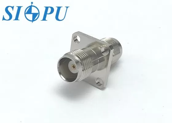
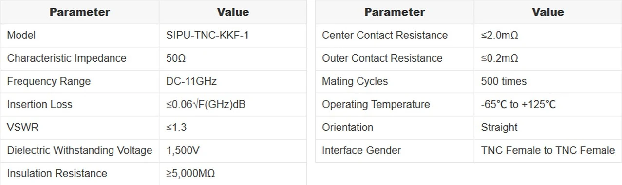
A TNC female to female adapter flange has two ports for radio waves. It joins two male tnc connectors together because it has two female TNC ports, and a flange body holds it to a panel. The interface is set out in IEC 61169-17, and TNC stands for Threaded Neill-Concelman. The threaded coupling holds better than a bayonet design, which is why TNC connectors are used in machines that shake. Our SIPU-TNC-KKF-1 is oriented straight and has a characteristic impedance of 50 Ω. This means that the signal goes through the wall without changing its impedance.
Internal Construction
In a TNC female to female adapter flange, the RF line is made up of four parts. The SIPU-TNC-KKF-1's outer conductor is made of nickel-plated brass, which doesn't rust and helps with shielding. The middle wire is made of gold-plated beryllium bronze, which was picked because it has low contact resistance and stable electrical performance. An PTFE insulator keeps the center contact in place and makes sure that its electrical properties stay the same across a wide range of temperatures. Every dimension is set by precise CNC machining. At that point, even a small mistake in size changes the impedance, so grinding accuracy is directly linked to signal quality.
Where These Adapters Are Used
These parts are used by engineers in telecom base stations, remote radio heads, military field communication tools, test labs, and instruments for space and aviation. Two TNC cables are put inside and one is put outside of the enclosure in chassis and cabinet work. The same part is often used as a bulkhead pass-through. A TNC female to female adapter flange sends the load of the wire to the panel instead of the electronics inside. Most of the time, OEM engineers ask me two questions: will the hole pattern fit? and Will the part stay in place when it shakes?
The Main Factors That Affect TNC Female to Female Adapter Flange Signal Quality
Impedance Continuity and Internal Geometry
RF energy bounces back wherever the resistance changes. To explain this, microwave engineering books like Pozar's say that the impedance is set by the ratio of the outer conductor diameter to the center conductor diameter and the dielectric constant. The dielectric constant is set by the PTFE, so the weight is carried by the machined diameters. When you get close to the dielectric support, a small gap or step can make a reflection that shows up as a rise in VSWR at higher frequencies. The SIPU-TNC-KKF-1 keeps its VSWR at 1.3 from DC to 11 GHz. That's a return loss of about 17.7 dB, which is about 1.7% of the power that was incident.
Insertion Loss and Frequency
Because conductor and dielectric losses go up with frequency, so does insertion loss. It says that the SIPU-TNC-KKF-1 has a dB value of 0.06√F(GHz). That's about 0.06 dB at 1 GHz, 0.15 dB at 6 GHz, and 0.20 dB at 11 GHz. That way, you can figure out how much link loss the TNC female to female adapter flange will cost. The tenths of a decibel add up over several panel changes if your system is near the top of the band. Not just the center frequency, but also your highest working frequency should be used to check the figure.
Plating, Contact Condition, and Environment
The thickness of the plating and how well it sticks determine how a finish ages. When nickel and gold are thin or flake off, they make the contact resistance higher. Over time, rust adds noise and loss. The SIPU-TNC-KKF-1 says that the resistance of the center contact is ≤2.0 mΩ and the resistance of the outer contact is ≤0.2 mΩ. The finish is the same from one production batch to the next because the metal thickness and binding strength are checked on each batch. Contact quality can be changed by dirt on the surface, wear after 500 mating cycles, shaking, and temperature changes from -65°C to +125°C. The rating should be seen as a limit, not a goal.
Mechanical Design and Mounting Factors That Influence RF Performance
Flange Fit and Hole Pattern
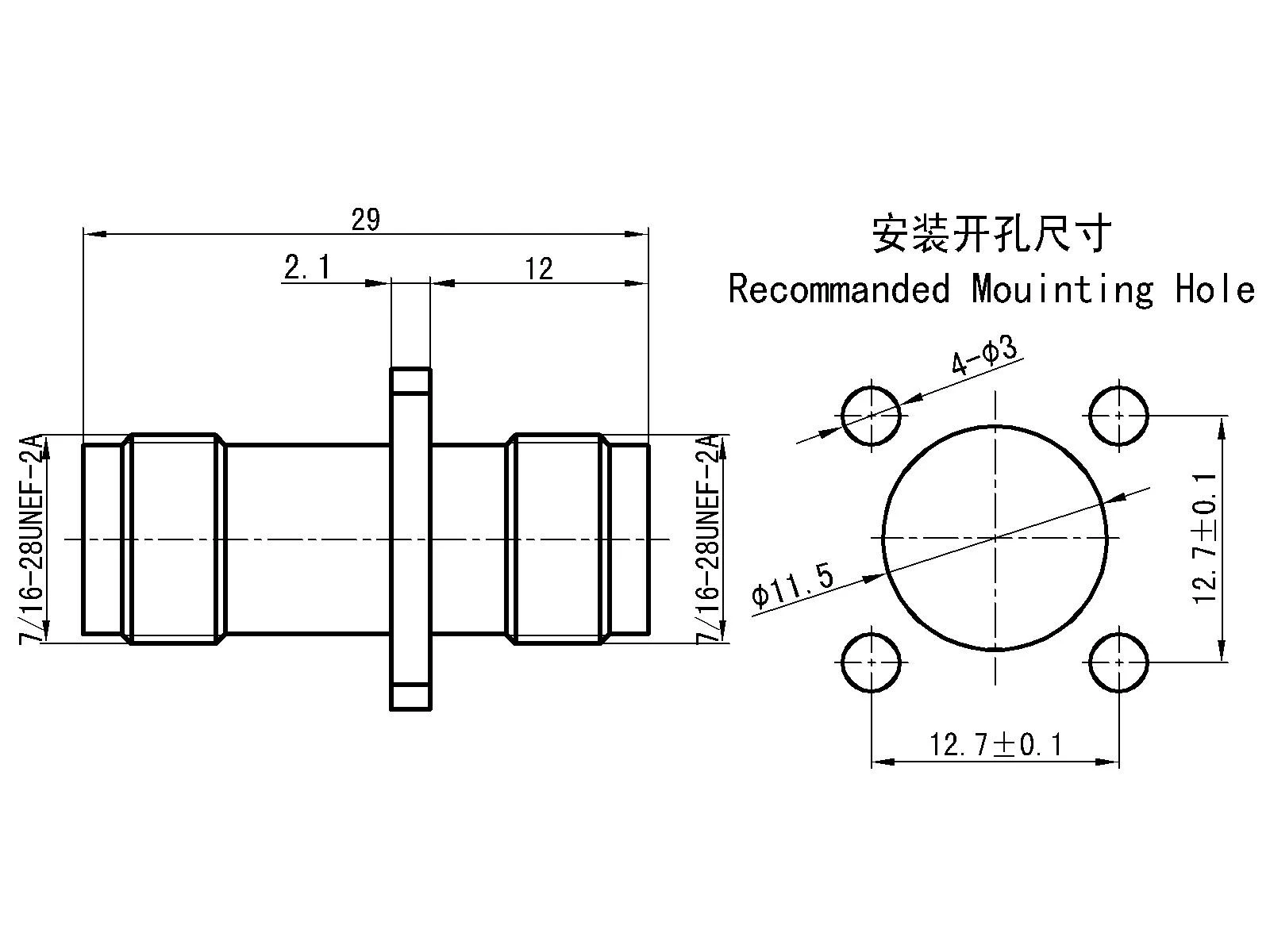
The flange is not just a bracket; it is part of the RF path. People who put the part in place force it into place, which puts stress on the contacts if the hole spacing, flange thickness, or cutout size don't match the panel. The mating cable can also pull at an angle if the ports are not lined up right. OEM teams that buy a lot of pieces should make sure the hole drawing is correct before they get the first sample. SIPU lets you change the way the mechanical design works, so a flange can fit into your panel drawing instead of the other way around.
Grounding and Shielding Continuity
It's important for the outer conductor to make steady touch with the panel over and over again for the shield current to flow through the wall. It is possible for paint, anodizing, or rust under the flange to block that path, which would allow interference to flow around the connection. Surface metal that is bare and clean and even screw pressure are both good. Putting a flange on a grounded panel adds electromagnetic shielding and lowers interference, which has an effect on how well the whole system works. The nickel plating on the outside of the body keeps that joint from rusting. For closed units, get your RF and structure experts to agree on the plan for the gasket and finish at the same time.
Torque, Vibration, and Installation Care
The threaded coupling is better at stopping vibrations than bayonet fittings, but only if it is fully mated by the fitters. When you cross-thread, side-load, or over-tighten, you break the threads and bend the center contact. When you under-tighten, the nut can come loose during vibration, and a joint that is too loose can cause the signal to go out and on. Before mating, clean both surfaces and apply the coupling force that was given. Instead of judging by feel, use a torque wrench in production. This way, the RF results will be the same across hundreds of assemblies when the torque is the same. Hold up heavy cables so that they don't hang off the flange.
How to Diagnose Poor Signal Quality in a TNC Female to Female Adapter Flange
Define the Symptom First
Before you touch the hardware, write down what you see. Different problems can be caused by things like high VSWR, extra loss, drop-outs that happen from time to time, loss at certain frequencies only, and mechanical looseness. A mismatch or a broken contact is often the cause of a high VSWR. Behavior that comes and goes can mean that a nut is loose or the ground is bad. Loss that gets worse with frequency could mean that there is damage or contamination close to the dielectric. At the time of the fault, write down the temperature, amount of vibration, and type of wire. This is important because a TNC female to female adapter flange is only one link in the chain.
Inspect and Measure
The first thing you should do is look at the threads, center contact, plating, flange line, and fastening screws. Check for broken contacts, dirt, scratches, and metal that is worn down. Then, use a calibrated vector network analyzer to take measurements across the whole range of operation. Set the reference adapter to a known good value and record the insertion loss and VSWR or return loss. Look at the limit given in the datasheet, like VSWR ≤ 1.3 for the SIPU-TNC-KKF-1. If there is a difference between the two readings, it means that there is a problem with how the adapter is mounted.
Isolate the Root Cause
A lot of the problems people think are caused by the adapter are actually caused by cables, fixings, antennas, and ground lines. Change the part that might be broken with one that has been proven to work, and check to see if the problem moves with the part or stays with the system. While looking at the trace, gently bend the cable, and tap the panel to make the vibration effects happen again. If the fault goes beyond the adapter, write down how it failed and send the part and the test trace to your supplier. You can expect a response from our technical team within 12 hours, which is helpful when a project milestone is coming up soon.
TNC Female to Female Adapter Flange Compared with Alternatives and Selection Criteria
Flange Versus Barrel Adapters
A barrel adapter lets two cables connect without any problems. It works for temporary and tabletop links, but it doesn't have a panel mount, so the weight of the cables and their movement put direct stress on the connections. You can fix the joint to the chassis with a TNC female to female adapter flange. This provides a consistent ground path and keeps the internal wiring from being stressed. If the connection goes through a wall, the equipment is likely to shake, or the installations need to be consistent on an assembly line, choose the flange. If quick rearrangement is more important than mechanical steadiness, choose a barrel.
TNC Versus SMA and N-Type
SMA connectors are smaller, and many types can handle higher frequencies. However, their small coupling nut is not as strong. Designers often choose N-type connectors for outdoor or high-power runs because they are bigger. TNC is a threaded 50 Ω interface that is stronger than SMA but smaller than N-type. It works with the SIPU-TNC-KKF-1's DC to 11 GHz range. Before you switch families, you should look at the impedance, frequency, power handling, panel space, and connections that are already on your cords. With each extra adapter, there is one more point of reflection.
Selection Criteria for OEM Panels
Start with the application and make a list of your needs, such as the type of interface, the 50 Ω impedance, the highest frequency, the insertion loss limit, the VSWR target, the temperature range, the plating, and the flange dimensions. Then ask for a sample, a dimensional drawing, and the datasheet. Find out what the supplier can do for you in terms of customization, RF testing, machining, and plating control. Leave some space. Getting an 11 GHz part is a good idea if your system's fastest speed is 8 GHz. SIPU can make both prototype samples and large quantities, so a design can go from being approved for samples to being made in large quantities.
Procurement and Quality Verification for Bulk Orders
What Drives Price and Lead Time
The price shows more than just the type of connector. It's important to think about the material, plating, tolerance, RF testing, special flange work, order number, packing, and shipping terms. SIPU makes and exports goods all at once, which keeps the price of a TNC female to female adapter flange in bulk low. Standard RF connectors can be shipped from stock and arrive in 72 hours, and special goods are made on separate lines with priority operations. For buyers in the US, our partner JNP Supplies LLC in Seattle, Washington, helps with project planning and communication. Share drawings and estimate amounts early on because a revision-controlled drawing keeps you from having to re-quote and wait.
Batch Consistency and Plating Control
When there are hundreds of parts in a lot, batch-to-batch plating variation is a real worry for many buyers. Checking the thickness of the metal and the strength of the bonding are done on every SIPU production batch. Every batch is also tested for RoHS compliance. Dielectric withstanding voltage testing confirms that it can handle 1,500 V, and insulation resistance testing confirms that it is higher than 5,000 MΩ. A quality management system that is ISO 9001 certified guides our production. Tell us what inspection items your quality team needs when you ask for a quote for a TNC female to female adapter flange. That way, we can make sure they fit with your acceptance plan.
Incoming Inspection Checklist
When it arrives, check the part number, quantity, packaging, flange size, hole pattern, threads, center contacts, and the way the plating looks. Pull a sample to use a calibrated analyzer to test for insertion loss and VSWR in the radio frequency range. Check the fit, retention, and coupling torque of the connecting surfaces, and do a test fit on a real panel. You may also have to test for salt spray according to ASTM B117 or sinusoidal vibration according to IEC 60068-2-6. Keep inspection records, approved drawing changes, and batch numbers all in one place so that you can easily connect any problems that come up in the future to a specific lot.
Conclusion
A TNC female to female adapter flange's signal strength is affected by a number of things that work together. The ≤0.06√F(GHz) dB figure shows that insertion loss goes up with frequency, while VSWR and return loss are set by impedance continuity and machining geometry. Over time, plating, contact condition, cleanliness, and temperature can change how resistant a contact is. Just as important is the mechanical fit. The joint stays stable when it vibrates if it has the right hole pattern, a clean grounded connection to the panel, and the right coupling torque. A structured analysis using a calibrated tester can tell the difference between problems in the adapter and those in the wire or system. The flange is better for panel pass-through work that needs stable grounding than the barrel, SMA, and N-type choices. When you choose based on frequency, drawing, and batch inspection needs, you get consistent results throughout a production run.
FAQ
1. What impedance and VSWR does the SIPU-TNC-KKF-1 offer?
The resistance is 50 Ω, and the VSWR is ≤1.3 across DC to 11 GHz.
2. How much insertion loss should I expect at 11 GHz?
Up to 0.06√F(GHz) dB, or about 0.20 dB at 11 GHz, is the most that can happen.
3. Why does torque affect signal quality?
Under-tightening makes VSWR higher because it lets the connection nut come loose when the system shakes. If you tighten too much, you could damage the threads and the center contact. Clean the connections and use the force that is given.
4. How many mating cycles does the adapter support?
It is possible for the SIPU-TNC-KKF-1 to mate 500 times.
5. Can the flange follow my panel drawing?
SIPU allows for customization of mechanical design, as well as production in large quantities and test models. Send us your drawing and the number of items you want.
Request a TNC Female to Female Adapter Flange Supplier Quote from SIPU
Let SIPU know about your plan, frequency range, and how many TNC female to female adapter flange you need for your next chassis or panel job. Our team responds within 12 hours, can help with both prototypes and mass production, and can make changes to both the electrical and mechanical designs. If you want a datasheet, sample, or quote for the SIPU-TNC-KKF-1, email info@sipu-rf.com or go to sipuconn.com.
References
1. IEC 61169-1, Radio-Frequency Connectors – Part 1: Generic Specification, 2013
2. IEC 61169-17, Radio-Frequency Connectors – Part 17: Sectional Specification for rf coaxial connectors with Screw Coupling (Type TNC), International Electrotechnical Commission
3. Pozar, D. M., Microwave Engineering, 4th Edition, Wiley, 2011
4. ASTM B117, Standard Practice for Operating Salt Spray (Fog) Apparatus, 2019
5. IEC 60068-2-6, Environmental Testing – Part 2-6: Tests – Test Fc: Vibration (Sinusoidal), 2007
6. ASTM B568, Standard Test Method for Measurement of Coating Thickness by X-Ray Spectrometry, 1998
Contact us directly for customized solutions, quotations and long-term strategic cooperation.