- English
- French
- German
- Portuguese
- Spanish
- Russian
- Japanese
- Korean
- Arabic
- Greek
- German
- Turkish
- Italian
- Danish
- Romanian
- Indonesian
- Czech
- Afrikaans
- Swedish
- Polish
- Basque
- Catalan
- Esperanto
- Hindi
- Lao
- Albanian
- Amharic
- Armenian
- Azerbaijani
- Belarusian
- Bengali
- Bosnian
- Bulgarian
- Cebuano
- Chichewa
- Corsican
- Croatian
- Dutch
- Estonian
- Filipino
- Finnish
- Frisian
- Galician
- Georgian
- Gujarati
- Haitian
- Hausa
- Hawaiian
- Hebrew
- Hmong
- Hungarian
- Icelandic
- Igbo
- Javanese
- Kannada
- Kazakh
- Khmer
- Kurdish
- Kyrgyz
- Latin
- Latvian
- Lithuanian
- Luxembou..
- Macedonian
- Malagasy
- Malay
- Malayalam
- Maltese
- Maori
- Marathi
- Mongolian
- Burmese
- Nepali
- Norwegian
- Pashto
- Persian
- Punjabi
- Serbian
- Sesotho
- Sinhala
- Slovak
- Slovenian
- Somali
- Samoan
- Scots Gaelic
- Shona
- Sindhi
- Sundanese
- Swahili
- Tajik
- Tamil
- Telugu
- Thai
- Ukrainian
- Urdu
- Uzbek
- Vietnamese
- Welsh
- Xhosa
- Yiddish
- Yoruba
- Zulu
What Is an SBMA Female Right-Angle Flange Mount Connector?
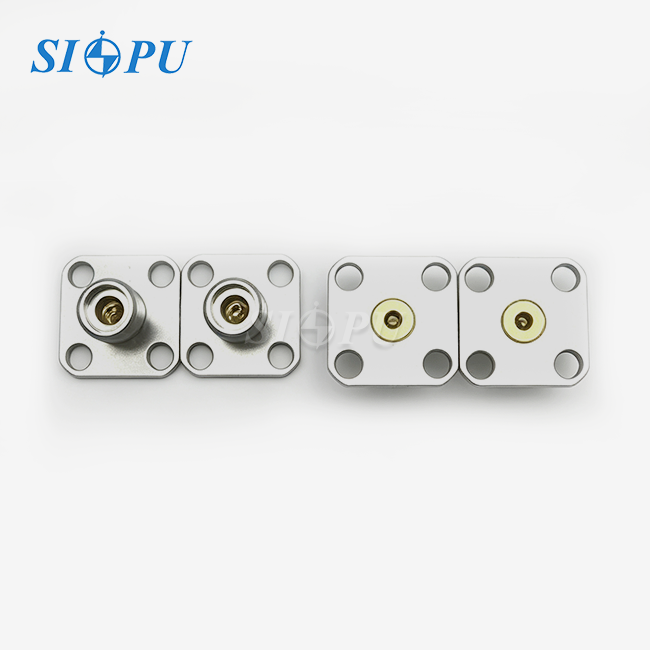
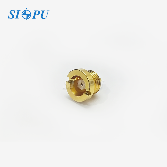
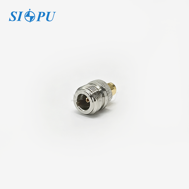
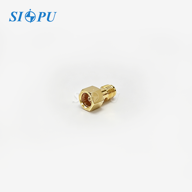
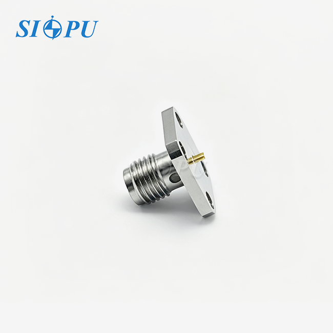
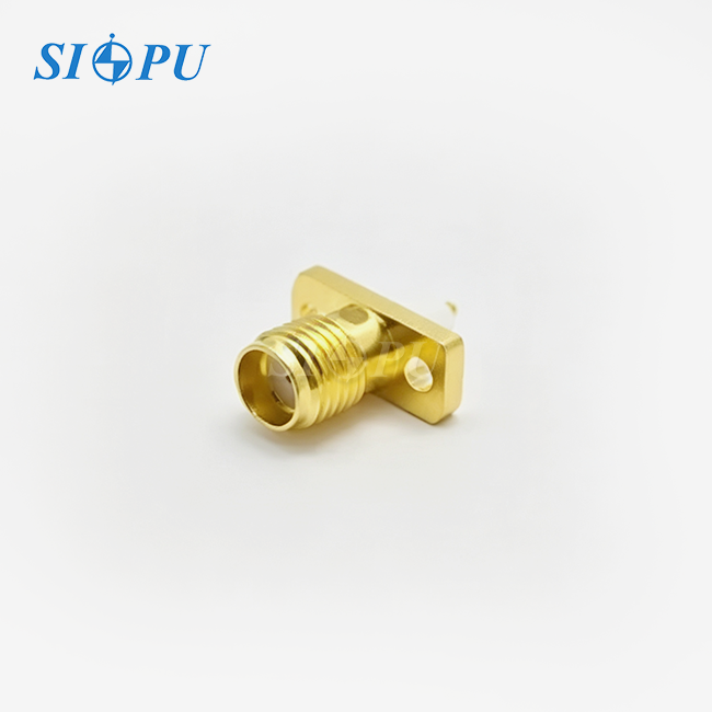
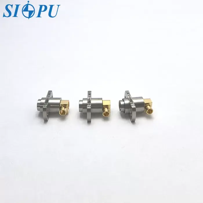
An SBMA female right-angle flange mount connector is a precision RF interconnect built on the subminiature BMA interface standard. It uses a slide-on (push-on) mating mechanism — no threading required — making it ideal for high-density backplane assemblies where manual torquing is physically impossible. The 90-degree body redirects cables parallel to the mounting board, reducing Z-height. The flange base bolts directly to a chassis panel for rigid mechanical retention. SIPU's model SIPU-SBMA-KWFB2G-1 covers DC to 28 GHz at 50 Ω impedance, rated for ≥500 mating cycles across −65 °C to +125 °C operating temperatures.
Understanding SBMA Female Right-Angle Flange Mount Connectors
Interface Standard and Family Context
The BMA (Blind-Mate A) interface is where the SBMA interface comes from. The BMA interface is based on IEEE 287 and is in the same slide-on socket family as SMP. When two SBMA connectors are mated, they automatically line up. This lets the axial float (±0.51 mm usual) and radial float account for mechanical errors in automatic or high-density setups. This is not the same as SMA or SMB connections, which use threaded coupling.
Key Electrical Specifications
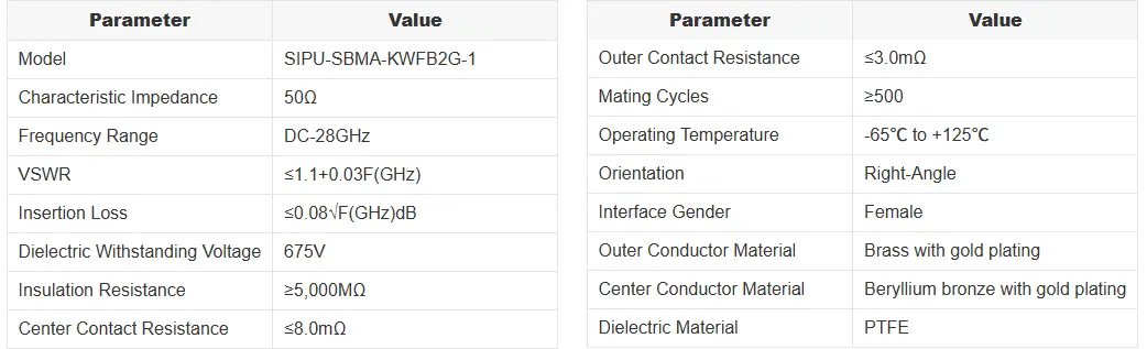
The SBMA female right-angle flange mount connector from SIPU (SIPU-SBMA-KWFB2G-1) has a VSWR of 1.1 + 0.03F(GHz) and an insertion loss of 0.08√F(GHz) dB from DC to 28 GHz. The dielectric voltage is 675 V, the insulation resistance is more than 5,000 MΩ, and the contact resistance is 8.0 mΩ in the middle and 3.0 mΩ on the outside. These numbers are good enough for 5G backhaul, radar T/R modules, and high-speed test equipment to make sure signals are still strong.
Materials and Construction
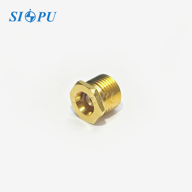
For spring retention and conductivity, the center conductor is made of beryllium bronze (BeCu) that has been plated with gold. The outer wire is made of brass that has been plated with gold to protect it from rust. Signal loss is low across the whole frequency range thanks to the PTFE dielectric. The right-angle body, which is made with precise CNC machining, works with RG405 cables and others that are the same or similar. The flange mount, which usually has two or four holes, holds the connection to a frame panel so it doesn't move around.
Identifying Genuine Connectors
Look for proof of ISO 9001 certification, plate inspection records that can be traced back to a specific batch, and compliance with IEEE 287 interface gaging for size. Genuine SBMA female right angle flange mount connections have a constant gold layer thickness when inspected with XRF, and they can handle a voltage of 675 V without breaking.
Comparing SBMA Female Right-Angle Flange Mount Connectors with Alternatives
SBMA vs. SMA and SMB
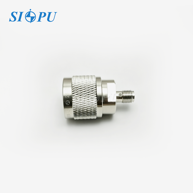
Threaded interfaces are used by SMA connectors, and they work reliably up to 18 GHz. A snap-on interface that is usually rated to 4 GHz is used by SMB connectors. The SBMA female right-angle flange mount connector works with frequencies from DC to 28 GHz and has a slide-on mechanism designed for blind-mating in multi-port arrays. Neither the SMA nor the SMB can do this on a large scale without a lot of extra work.
Right-Angle vs. Straight Orientation
When you mount an SBMA socket, the straight end sticks out straight, so the wire needs to be able to move up and down. The version with a right angle leaves parallel to the board. This lowers the module's height and makes it easier to handle wires in frames that are placed on a rack. When it comes to dense backplane assemblies or phased-array radar front ends, this difference in Z-height means that a design might or might not fit a certain form factor.
Supplier Landscape
Global names like Amphenol, TE Connectivity, and HUBER+SUHNER make different levels of performance SBMA connections. SIPU RF Technology was established in 1998 and has more than 25 years of experience making products. Their SBMA female right-angle flange mount connector works at DC–28 GHz and comes with ISO 9001-certified batch quality control, standard delivery in 72 hours, and direct OEM/ODM support. This gives procurement teams a reliable way to go from comparing samples to ordering in bulk.
Installation and Maintenance of SBMA Female Right-Angle Flange Mount Connectors
Flange Mounting Procedure
To connect a cable, place the flange plate flat on a machined chassis surface. To keep the panel from warping and causing the fitting contact to become out of alignment, torque the flange screws evenly in a cross pattern. Before you install the panel, make sure it is flat. A clean, flat seating surface is needed for the flange contact resistance of 3.0 mΩ. Once the flange is in place, run the RG405-compatible cable parallel to the board to keep stress from building up at the right-angle change.
Wiring and Soldering Practices
Cut the RG405 cable to the size required by the connector. To keep the PTFE dielectric from melting, solder the center contacts at the right temperature. If you overheat them, the dielectric deforms, which changes the impedance from 50 Ω. Before installing, look closely at the solder joints. Some common mistakes are cold solder joints that make the contact resistance higher than the ≤ 8.0 mΩ limit and uneven outer conductor crimps that make shielding less effective.
Ongoing Maintenance
Gold-plated BeCu contacts don't rust and don't need to be cleaned with chemicals when they're working normally. Check the flange screws for loosening after vibration or thermal cycling, and use a gentle push-pull check to make sure the connector is properly seated. In aerospace or defense installations that work between -65 °C and +125 °C, check the flange torque as part of regular maintenance to keep the EMI shielding going.
Procurement Insights: How to Buy SBMA Female Right-Angle Flange Mount Connectors
Evaluating Technical Requirements
Before issuing an RFQ, confirm frequency range (DC–28 GHz for this series), impedance (50 Ω), cable compatibility (RG405 or equivalent), mating cycle requirement (≥500), and operating temperature (−65 °C to +125 °C). For backplane OEM programs, request sample units for VSWR and insertion loss comparison against incumbent suppliers. SIPU supports mixed-price sample orders with engineering trial documentation to accelerate design qualification.
Pricing and Batch Consistency
Material selection drives price: gold-plated BeCu contacts and precision CNC-machined brass bodies sit at a higher cost point than lower-grade alternatives, but they deliver the contact resistance and spring force consistency that prevents batch-to-batch VSWR drift. Request plating thickness reports (XRF data) and batch-level insulation resistance test records as standard deliverables — these documents are the fastest way to identify suppliers who maintain dimensional and electrical consistency across production runs.
Sourcing Through SIPU
SIPU RF Technology ships standard SBMA female right-angle flange mount connectors within 72 hours from its Xi'an facility. Custom configurations receive priority production line scheduling. U.S.-based customers work through SIPU's North American partner, JNP Supplies LLC (Seattle, WA), for localized coordination. SIPU's product portfolio at sipuconn.com covers SMA, SMP, SMPM, SSMP, MCX, MMCX, BNC, TNC, N, and other RF connector series alongside this SBMA series.
Applications and Future Trends of SBMA Female Right-Angle Flange Mount Connectors
Current Deployment Areas
The main areas where this type of connector is used are listed below:
- Telecom backplane systems: High-density 5G base station chassis use the slide-on blind-mate interface to reduce assembly time across hundreds of port positions simultaneously, where threaded connectors would require impractical labor hours.
- Phased array radar and electronic warfare: T/R module backplanes in defense systems require simultaneous multi-point mating; the −65 °C to +125 °C rating and ≥500 mating cycle durability match military environmental qualification requirements.
- Automated test equipment (ATE): ATE platforms cycle DUT boards repeatedly; the SBMA female right-angle flange mount connector's slide-on interface eliminates the thread wear that limits SMA-based ATE systems over extended test campaigns.
Autonomous test equipment (ATE): ATE platforms regularly run DUT boards through their paces. The SBMA female right-angle flange mount connector's slide-on interface gets rid of the thread wear that stops SMA-based ATE systems from running for long test programs.
Emerging Trends
One thing that all of these areas of use need is consistent electrical performance over many mating events while being mechanically stressed. This is directly dealt with by the SIPU-SBMA-KWFB2G-1's BeCu contact spring geometry and precisely machined interface dimensions.
Conclusion
The SBMA female right-angle flange mount connector has a clear job to do: it connects two RF devices without touching them in places with a lot of vibration and high density from DC to 28 GHz. Its right-angle shape lowers the module's height, its flange base makes it easy to attach to a chassis, and its BeCu gold-plated contacts keep their electrical performance stable over ≥500 mating cycles at temperatures ranging from -65 °C to +125 °C. When purchasing engineers look at backplane interconnects, having batch quality paperwork that can be checked and quick sample turnaround makes the seller approval process faster and less risky.
FAQ
1. How does the SBMA female right-angle flange mount connector differ from SMP?
Both belong to the slide-on blind-mate family. SMP typically operates to 40 GHz and uses a snap-on interface with a defined retention force. SBMA uses a push-on slide interface with greater axial and radial float tolerance, making it better suited to high-density multi-port blind-mate backplane applications where alignment tolerance stacking is a concern.
2. What cable types are compatible with this connector?
SIPU's SIPU-SBMA-KWFB2G-1 is compatible with RG405 (0.086" semi-rigid) and equivalent-specification cables. Confirm cable outer diameter and dielectric dimensions against connector termination drawings before assembly.
3. How do I verify batch consistency when ordering in volume?
Request XRF plating thickness reports, batch-level insulation resistance test data (≥5,000 MΩ), and contact resistance measurements (≤8.0 mΩ center, ≤3.0 mΩ outer) as standard documentation with each production batch. SIPU's ISO 9001 quality system generates these records for every run.
4. Is this connector export-controlled?
SBMA connectors of this specification typically classify as EAR99 under U.S. Export Administration Regulations. Verify classification against your specific end-use and destination before export.
5. What is the lead time for custom flange configurations?
Standard products ship within 72 hours. Custom mechanical configurations receive priority production scheduling; contact info@sipu-rf.com with your drawing or specification for a lead time quote.
Get Your SBMA Female Right-Angle Flange Mount Connector from SIPU
SIPU RF Technology makes the SBMA female right-angle flange mount connector for DC to 28 GHz. They have ISO 9001-certified batch control, standard delivery in 72 hours, and full OEM/ODM support. SIPU's engineering team gets back to you within 12 hours, whether you need samples for design approval or a lot of parts for a backplane program. You can look at full specs and ask for a price at sipuconn.com, or you can email info@sipu-rf.com.
References
1. IEEE Standard 287-2007 — IEEE Standard for Precision Coaxial Connectors (DC to 110 GHz). IEEE, 2007.
2. Straw, R. D. (Ed.). The ARRL Antenna Book. American Radio Relay League, 2019.
3. Pozar, D. M. Microwave Engineering, 4th ed. Wiley, 2011.
4. MIL-PRF-31031 — Performance Specification: Connectors, Radio Frequency, Blind Mating. U.S. Department of Defense, 2003.
5. Wadell, B. C. Transmission Line Design Handbook. Artech House, 1991.
6. RF & Microwave Connector Market Report. IHS Markit (now S&P Global), 2022.
Contact us directly for customized solutions, quotations and long-term strategic cooperation.