- English
- French
- German
- Portuguese
- Spanish
- Russian
- Japanese
- Korean
- Arabic
- Greek
- German
- Turkish
- Italian
- Danish
- Romanian
- Indonesian
- Czech
- Afrikaans
- Swedish
- Polish
- Basque
- Catalan
- Esperanto
- Hindi
- Lao
- Albanian
- Amharic
- Armenian
- Azerbaijani
- Belarusian
- Bengali
- Bosnian
- Bulgarian
- Cebuano
- Chichewa
- Corsican
- Croatian
- Dutch
- Estonian
- Filipino
- Finnish
- Frisian
- Galician
- Georgian
- Gujarati
- Haitian
- Hausa
- Hawaiian
- Hebrew
- Hmong
- Hungarian
- Icelandic
- Igbo
- Javanese
- Kannada
- Kazakh
- Khmer
- Kurdish
- Kyrgyz
- Latin
- Latvian
- Lithuanian
- Luxembou..
- Macedonian
- Malagasy
- Malay
- Malayalam
- Maltese
- Maori
- Marathi
- Mongolian
- Burmese
- Nepali
- Norwegian
- Pashto
- Persian
- Punjabi
- Serbian
- Sesotho
- Sinhala
- Slovak
- Slovenian
- Somali
- Samoan
- Scots Gaelic
- Shona
- Sindhi
- Sundanese
- Swahili
- Tajik
- Tamil
- Telugu
- Thai
- Ukrainian
- Urdu
- Uzbek
- Vietnamese
- Welsh
- Xhosa
- Yiddish
- Yoruba
- Zulu
2.92mm Male to 2.4mm Female Gold-Plated Adapter: Fit and Mating
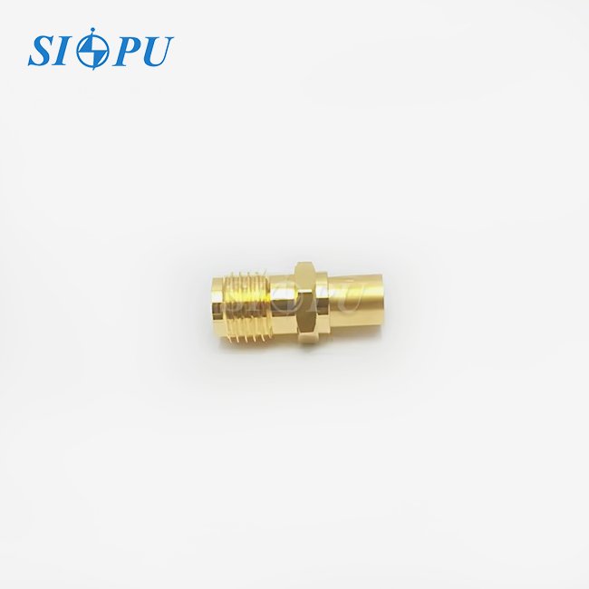
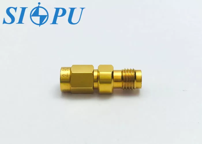
A 2.92mm male to 2.4mm female gold-plated adapter fits by joining a 2.92mm female port on one side to a 2.4mm male connector on the other, while holding a 50 Ω path from DC to 40 GHz. Good fit relies on right gender, matching thread and pin geometry, clean faces, and regulated torque. Our type SIPU-2.92/2.4-JK is a straight adapter with a PEI dielectric and a VSWR limit of ≤1.05 + 0.008F(GHz). Small details influence the outcome. In this post, I explain how mating works, what to verify on a datasheet, and how to safeguard pricey test ports and measurement accuracy.
What Is a 2.92mm Male to 2.4mm Female Gold-Plated Adapter?
Interface Conversion in Plain Terms
A 2.92mm male to 2.4mm female gold plated adapter converts one kind of precision coaxial interface into another.The 2.92mm side (commonly called K-type) is mechanically compatible with SMA and 3.5mm connectors and mates with a 2.92mm female port.The 2.4mm side is a female port that accepts a 2.4mm male connector.The interface is IEC 61169-40 specified and rated to 50GHz.The two series are not intended to join directly, therefore the adapter takes away the need to force them together.The lower interface is the overall rating of the part, so SIPU defines it as DC to 40 GHz.
Where Labs and OEMs Use It
I most usually encounter this component between a vector network analyzer and a device under test.A VNA port or cable has a 2.92mm , yet the module , antenna or filter has a 2.4mm connector .Other applications include spectrum-analyzer setups, millimeter-wave module characterization, semiconductor research and 5G and 6G lab benches.It’s used in aerospace and military teams in fixtures that see wide temperature swings.Its tiny size and remarkable resilience to vibration make it perfect for crowded benches and high density routing.A 2.92mm male to 2.4mm female gold-plated adapter also suits production test stations where the 500+ mating-cycle rating is important.
What Gold Plating Does and Does Not Do
Gold coating on a 2.92mm male to 2.4mm female gold-plated adapter inhibits oxidation, so contact resistance maintains steadier than it does on bare metal. Here, both the brass outer conductor and the beryllium bronze central contact bear gold coating. Center contact resistance is ≤4.0 mΩ, while outside contact resistance is ≤2.5 mΩ. Plating alone does not establish RF performance, however. Thickness, base material, dimensional precision, and internal design all contribute. ASTM B488 classifies electrodeposited gold coatings for engineering usage, so purchasers may discuss plating in agreed language. Our staff verifies gold thickness and adhesion strength by batch sampling.
2.92mm Male and 2.4mm Female Fit and Mating Compatibility
Check Gender and Port Orientation
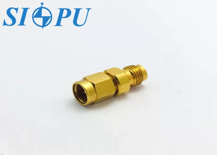
Start with the ports on your equipment. The 2.92mm male to 2.4mm female gold-plated adapter has a male end that fits into a female 2.92mm port, such as a cable end or VNA test port. The 2.4mm female side accepts the 2.4mm male connection on your device. If the port on your device is female then you will require an opposite gender connection. Both ends are terminated with 50 Ω impedance for minimal reflection and measuring error. Check the drawings or photos before ordering. Trace the full signal line, so that no junction mixes genders by accident.
Mating Steps and Torque
When I put on a 2.92mm male to 2.4mm female gold plated adapter I usually recommend the same manner. Examine both faces in strong light and wipe off any dust with a lint-free swab and isopropyl alcohol. Parts align straight, no side load. Hand start the coupling nut. Turn just the nut until seated. Finish with a calibrated torque wrench. Many accurate 2.92 mm and 2.4 mm connections need roughly 8 in-lb (0.9 N·m). Please consult your connector supplier or our specialists. Do not spin the adapter body. This can harm the gold plating and limit the life of the contact.
Common Mistakes and How to Avoid Them
Most failures boil down to a few habits. Picking a connection that looks like a 2.4mm or other exact interface damages threads and center pins. Overtightening bends connections, dirt increases contact resistance, and cross-threading results from misalignment. Cover unused connections. Store each 2.92mm male to 2.4mm female gold plated adapter in a clean, dry environment between -65 ℃ and +125 ℃. Prior to each new setup verify both ports against the designs. Those characteristics help prevent worn plating, inconsistent readings and downtime, all critical on a bench where one broken port might stop a project.
Key Specifications and RF Performance
Specifications at a Glance
Here are the published specifications for the SIPU-2.92/2.4-JK, a 2.92mm male to 2.4mm female gold-plated adapter built for DC to 40 GHz.
| Parameter | Value |
|---|---|
| Impedance | 50 Ω |
| Frequency range | DC–40 GHz |
| VSWR | ≤1.05 + 0.008F(GHz) |
| Insertion loss | ≤0.05√F(GHz) dB |
| Dielectric withstanding voltage | 500 V |
| Insulation resistance | ≥5,000 MΩ |
| Contact resistance | Center ≤4.0 mΩ; outer ≤2.5 mΩ |
| Mating cycles | ≥500 |
| Temperature range | -65 ℃ to +125 ℃ |
| Materials | Gold-plated brass, gold-plated beryllium bronze, PEI dielectric, silicone rubber seal |
Reading the VSWR and Insertion-Loss Limits
The limitations are formulae therefore I convert them into numbers. VSWR is maintained at or below 1.13 and insertion loss at or below 0.16 dB at 10 GHz. The limitations at 20 GHz are 1.21 and 0.22 dB. They are 1.37 and 0.32 dB at 40 GHz. The VSWR of 1.37 corresponds to around 16 dB return loss. These are upper limits for the entire 2.92mm male to 2.4mm female gold-plated adapter, not normal values, and allow you to budget error in a measurement chain. The relationship between VSWR, reflection coefficient and return loss is explained in Pozar’s Microwave Engineering.
Calibration Path and Test Data
Decide early whether a 2.92mm male to 2.4mm female gold plated adaptor is left within the calibration route or de-embedded. As explained in Agilent Application Note 1287-3, error correction establishes the measurement reference plane at the calibration point. If you calibrate with the adapter connected, use the same adapter setup during measurement. All SIPUs have a dielectric withstanding voltage of 500 V and insulation resistance ≥5,000 MΩ. Design controls VSWR and insertion loss. We don't examine these two parameters on a per unit basis. If your metrology team wants measured curves, please let us know the frequency points and format and we will check what we can provide.
Materials, Durability, and Environmental Limits
Brass, Beryllium Bronze, and PEI
The exterior conductor is brass with gold plating. The central contact is gold-plated beryllium bronze, a spring alloy that maintains its hold on the mating pin after prolonged usage. The dielectric is a polyetherimide (PEI). The qualities are stable in the rated range of -65 ℃ to +125 ℃, and it is completed with a silicone rubber sealing ring. Material certificates show the brass and beryllium bronze are spec-compliant. We also test each manufacturing batch for RoHS compliance; the legislation that sets these restrictions is EU Directive 2011/65/EU. This 2.92mm male to 2.4mm female gold plated adapter has a combination of conductivity, spring force and dimensional stability.
Gold-Plated Versus Stainless-Steel Adapters
Gold plated and stainless steel adapters are also available, the choice being dependent on the application. Gold plating resists oxidation and provides reliable electrical contact in laboratory and regularly changed test equipment. Stainless steel is more mechanically strong and can withstand rigorous use or industrial environment . Contact surfaces may still require plating . RF outcomes aren’t established alone by a finish. Dimensional Tolerance Center Pin Design Dielectric Concentricity Assembly Quality is More Important. This 2.92mm male to 2.4mm female gold-plated adapter suits laboratories that remate often. For harsher fixtures, compare lifecycle data, environmental specifications, and inspection records next to price. Standards such as MIL-STD-202 define common environmental test methods, so ask which ones a supplier has run.
What 500+ Mating Cycles Means
Our rating is ≥500 mating cycles. I treat that number as a wear budget. Each mating rubs the gold surface, so cleaning, straight alignment, and correct torque stretch the budget. Low, steady contact resistance is the practical sign of health: ≤4.0 mΩ at the center and ≤2.5 mΩ at the outer contact. Batch sampling of plating thickness and adhesion strength targets the contact wear that harms high-frequency performance. On a busy bench, log the mating count and retire the 2.92mm male to 2.4mm female gold-plated adapter before it nears the limit, so a worn part never sits between an expensive calibration kit and your device.
Choosing and Buying the Right Adapter
Straight or Right-Angle?
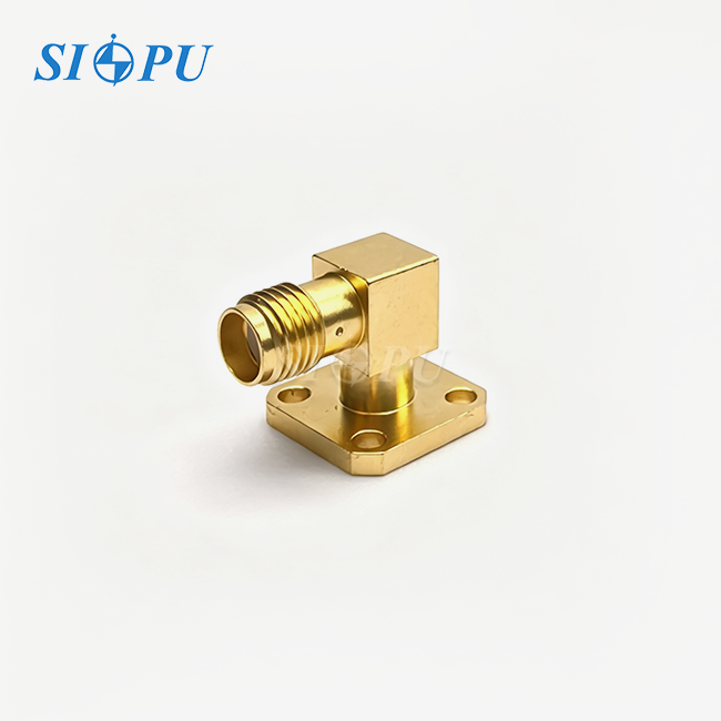
Straight 2.92 mm male to 2.4 mm female gold plated adapters are good for simple alignment and easy characterization and the SIPU-2.92/2.4-JK is a straight type with compact body for dense routing. Right-angle versions ease cable bends in tight fits, but add a curve and additional transition to the path. Put together a matrix with frequency capabilities , insertion loss , VSWR , dimensions , materials , durability , lead time , paperwork , and total cost . Buyers are more interested in continuity of supply and batch homogeneity. Engineers are more likely to place the most weight on RF data and drawings. Special requests for alternative length, orientation, plating or labeling are welcome.
Selection Checklist Before You Order
Here are the three checks I run before approving any 2.92mm male to 2.4mm female gold-plated adapter.
- Mechanical fit : Match your designs to the 2.92mm male and 2.4mm female interfaces, connection genders, thread size, orientation, equipment clearance and cable-routing requirements. If the documentation are outdated, photograph the actual ports. A mismatch identified at the bench costs much more than one found during review and it may damage an expensive test port.
- RF Performance: Before you accept it, check the 50 Ω impedance, frequency range, insertion loss, VSWR or return loss and calibration circumstances of your real band. Ask whether each restriction is a guarantyd max or usual value and if it applies to the complete adapter. Ask for repeatability or cycle life statistics if your bench remates regularly.
- Procurement records:- Materials, plating, drawings, sample results, lead time, minimum order quantity, warranty, quality records, packing, export and custom needed documentation. File the sample by part number so that incoming inspection and subsequent reorders all use the same reference and so that engineers may compare any fresh batch to the authorized sample.
These checks catch most late rejections before parts reach the bench.
RFQ, Samples, and Volume Supply
A clear request saves days. State the 2.92mm male to 2.4mm female gold-plated adapter configuration, 50 Ω, frequency range, maximum insertion loss, VSWR, materials, plating, orientation, dimensions, quantity, destination, and delivery date. Ask whether the part is stock or made to order and what drawings, reports and cycle data are provided. SIPU was founded in 1998 in Xi'an, with ISO 9001, CE and RoHS credentials, offering prototype samples and mass production. We have standard RF connectors in stock, ready for delivery in 72 hours and check availability for each model. JNP Supplies LLC is located in Seattle, Washington and is our partner servicing consumers across the United States and Canada. Try a sample order and let your team verify mating, clearance, torque and measuring performance before buying in bulk.
Conclusion
A 2.92mm male to 2.4mm female gold-plated adapter links a 2.92mm K-type port to a 2.4mm male connector, and its rating follows the lower interface, here DC to 40 GHz at 50 Ω. Good fit comes from checking gender and orientation, cleaning faces, aligning straight, and applying calibrated torque. The established limitations for VSWR and insertion-loss come down to unambiguous figures at each frequency . Calibration planning dictates whether the adapter remains in the measurement path . Gold plated brass, beryllium bronze, a PEI dielectric, and ≥500 cycles characterize durability but plating does not define RF outcomes. With a weighted checklist of fit, RF data and records, buyers may compare providers and avoid bench damage.
FAQ
1. Can I connect this adapter directly to SMA connectors?
The 2.92mm interface is mechanically compatible with SMA and 3.5mm connectors. This model transitions to 2.4mm, which needs a dedicated 2.4mm mate, so SMA connections call for a different adapter configuration.
2. What frequency range does this adapter cover?
This 2.92mm male to 2.4mm female gold-plated adapter covers DC to 40 GHz at 50 Ω, with VSWR ≤1.05 + 0.008F(GHz) and insertion loss ≤0.05√F(GHz) dB. Both are upper limits for the full adapter.
3. Why is gold plating used?
Gold resists oxide layers that raise contact resistance, which supports stable contact across 500+ mating cycles. Plating alone does not guarantee RF performance, so check the rest of the specification.
4. Does it suit high-density RF modules?
Yes. The straight, compact body fits crowded test setups and RF modules, and the secure connection structure resists accidental disconnection in vibration-prone settings. A 2.92mm male to 2.4mm female gold-plated adapter of this size still needs clearance for the mating connector.
Request a 2.92mm Male to 2.4mm Female Gold-Plated Adapter Quote from SIPU
Send your port details, frequency range, and quantity to SIPU at info@sipu-rf.com, and our engineers will check fit and mating for your setup. As a 2.92mm male to 2.4mm female gold-plated adapter manufacturer, we support prototype samples, volume production, and OEM changes, with a 12-hour inquiry response. U.S. buyers also get local coordination through JNP Supplies LLC in Seattle. Visit sipuconn.com for product details.
References
1. IEEE Standard for Precision Coaxial Connectors (DC to 110 GHz), IEEE Std 287, 2007
2. Pozar, D. M., Microwave Engineering, 4th Edition, Wiley, 2011
3. Agilent Technologies, Applying Error Correction to Network Analyzer Measurements, Application Note 1287-3, 2002
4. ASTM International, Standard Specification for Electrodeposited Coatings of Gold for Engineering Uses, ASTM B488, 2018
5. U.S. Department of Defense, Test Method Standard: Electronic and Electrical Component Parts, MIL-STD-202H, 2015
6. European Parliament and Council, Directive 2011/65/EU on the Restriction of Hazardous Substances in Electrical and Electronic Equipment (RoHS), 2011
Contact us directly for customized solutions, quotations and long-term strategic cooperation.