- English
- French
- German
- Portuguese
- Spanish
- Russian
- Japanese
- Korean
- Arabic
- Greek
- German
- Turkish
- Italian
- Danish
- Romanian
- Indonesian
- Czech
- Afrikaans
- Swedish
- Polish
- Basque
- Catalan
- Esperanto
- Hindi
- Lao
- Albanian
- Amharic
- Armenian
- Azerbaijani
- Belarusian
- Bengali
- Bosnian
- Bulgarian
- Cebuano
- Chichewa
- Corsican
- Croatian
- Dutch
- Estonian
- Filipino
- Finnish
- Frisian
- Galician
- Georgian
- Gujarati
- Haitian
- Hausa
- Hawaiian
- Hebrew
- Hmong
- Hungarian
- Icelandic
- Igbo
- Javanese
- Kannada
- Kazakh
- Khmer
- Kurdish
- Kyrgyz
- Latin
- Latvian
- Lithuanian
- Luxembou..
- Macedonian
- Malagasy
- Malay
- Malayalam
- Maltese
- Maori
- Marathi
- Mongolian
- Burmese
- Nepali
- Norwegian
- Pashto
- Persian
- Punjabi
- Serbian
- Sesotho
- Sinhala
- Slovak
- Slovenian
- Somali
- Samoan
- Scots Gaelic
- Shona
- Sindhi
- Sundanese
- Swahili
- Tajik
- Tamil
- Telugu
- Thai
- Ukrainian
- Urdu
- Uzbek
- Vietnamese
- Welsh
- Xhosa
- Yiddish
- Yoruba
- Zulu
SSMA Male Cable Assembly for RF Cable: Custom Design Guide
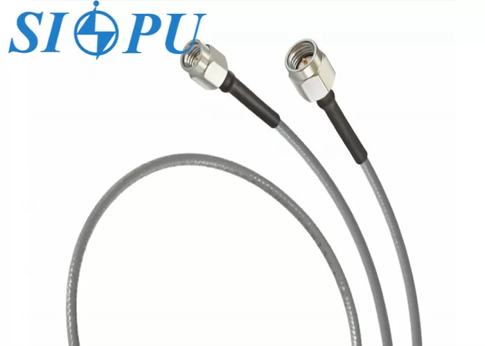
An SSMA male cable assembly for RF cable is a finished coaxial jumper that pairs a compact threaded SSMA male connector with a defined length of cable and is tested as one unit. A sound custom design starts with five decisions: impedance, frequency range, cable type, finished length with connector orientation, and the test records you need at delivery. SIPU's standard version runs from DC to 20 GHz at 50 Ω, with VSWR ≤1.4 and phase equalization within ±5°. This guide shows how I would specify, verify, install, and buy these assemblies for phased arrays, ground stations, and test systems.
What Defines an SSMA Male Cable Assembly for RF Cable
The Parts Inside a Finished Assembly
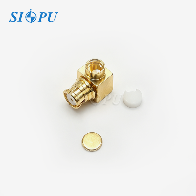
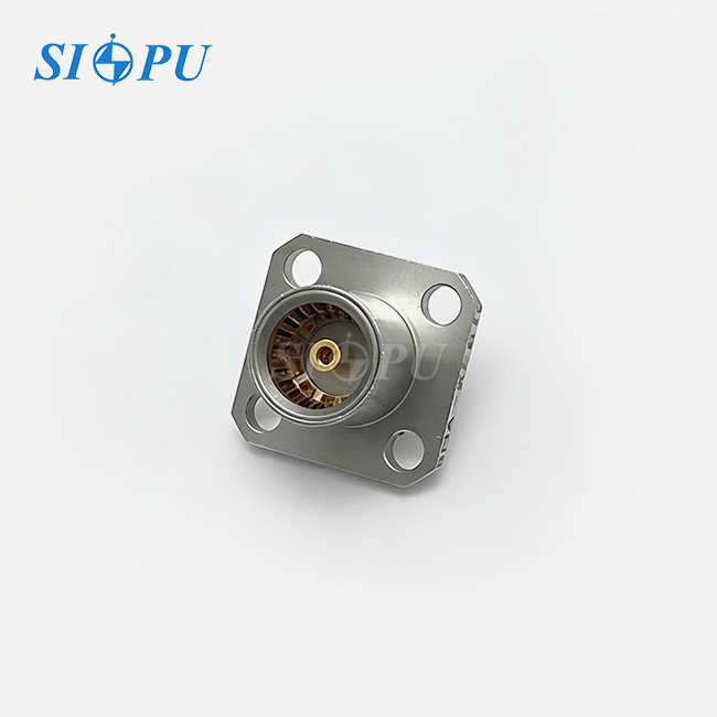
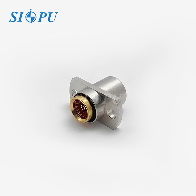
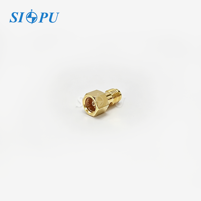
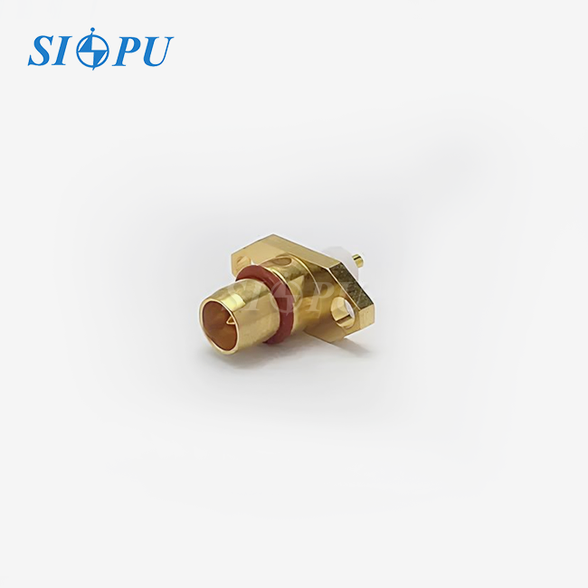
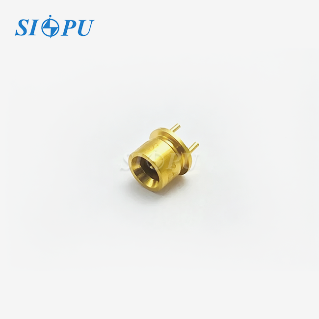
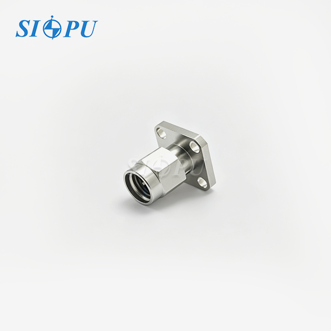
More than just a connector, a finished SSMA male cable assembly for RF cable. The connector body, center contact, dielectric insulator, coaxial cable, shielding braid, jacket, and the joint that connects them all are inside. Each part makes loss and phase worse or better. The SSMA family is related to SMA but smaller. It has a 1/10-36 thread, which means it can fit into thick panels and small modules where SMA hardware is too big. Because of this, it is often used in radar arrays, satellite payload modules, and bench fixtures. The work on the termination has the same effect on return loss as the connector, so I specify and inspect the whole assembly instead of just the connector.
Core Electrical Parameters of the SSMA Male Cable Assembly for RF Cable
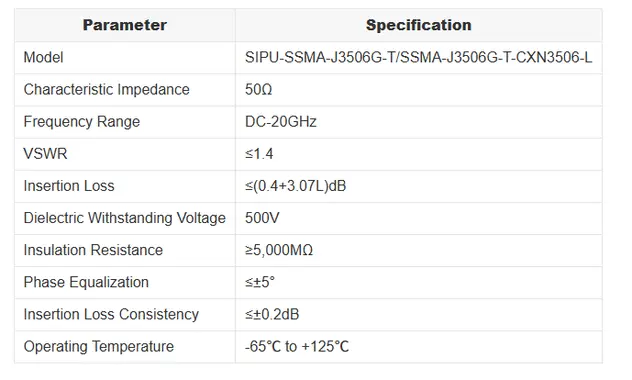
SIPU-SSMA-J3506G-T/SSMA-J3506G-T-CXN3506-L is our standard model, and it has the following specs: 50 Ω impedance, DC–20 GHz, VSWR ≤1.4, insertion loss ≤(0.4+3.07L) dB, 500 V dielectric withstanding voltage, and insulation resistance ≥5,000 MΩ. It has insertion loss stability of 0.2 dB and phase adjustment of ±5°. The last two numbers are very important for array builders to keep an eye on because they move the beam from channel to channel. Include all the numbers and the allowed length in the drawing. If a datasheet only shows typical values, there is room for disagreement when it comes to acceptance. So, make sure you know if each number is a guaranteed limit or just a typical result.
Environmental and Mechanical Limits
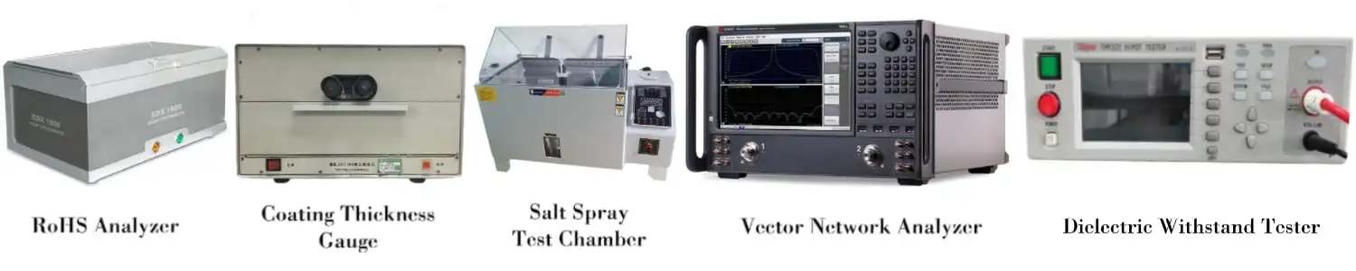
The temperature range for the assembly is -65°F to +125°F. Vibration, humidity, and corrosion are also important for phased-array and electronic warfare programs, so describe them in your RFQ. The cable is called CXN3506, and it works with RG316-type construction, which is a flexible coax that is common in this size of jumper. Flexible cable lets you choose how to run it. While semi-rigid cable holds its shape and phase better, it can't be bent back into shape after it has been formed. The decision should depend on whether the line will move after it is set up. We also check each production lot for RoHS compliance and make sure the plating thickness and bonding strength are correct at the batch level. This helps with rust resistance and long-term joining performance.
How to Choose and Compare SSMA Male Cable Assembly Designs
Match Cable and Connector Orientation to the Link
Start with the budget for the link. Note down the frequency, the amount of loss that is okay, the length of the path, and the area around the port. Flexible CXN3506 cable makes it easy to route for a short connection inside a rack. Ask for a right-angle body if the port faces a wall or is next to a heat sink. If you choose straight over right-angle, the cable will exit in a different direction, and you'll need to keep the bend radius free. Set this before the drawing is released. SIPU allows for custom specs and setup choices, so a custom SSMA male cable assembly for RF cable can be made to match your picture in terms of length, orientation, and end-connector pairing instead of having to make do with what's available in the catalog.
SSMA Versus SMA and MMCX
You can't use SSMA and SMA together. The SSMA thread is 1/10-36 and the SMA thread is 1/4-36, so they can't connect. Because it takes up less space on the board, thick modules choose SSMA. Snap-on interfaces are what MMCX is. It connects quickly, but it doesn't hold as well as a threaded coupling, which is a problem when the system is shaking. An SSMA joint with threads stays in place even when it is dropped or handled, making it good for radar and test stands. It is easier to find SMA hardware if the design can handle the bigger SMA footprint. The most useful threaded choice is SSMA if it can't be used. Verify that the mating port is SSMA female when purchasing an SSMA male cable assembly for RF cable.
Impedance, Flexibility, and Loss Class
The SIPU assembly is made of 50 Ω wires. The hardware in a 75 Ω system is different, so check your system's impedance first. The next comparison is between flexible and semi-rigid wire. Flexible cable can be handled many times, while semi-rigid cable provides more stable phase in a set run. Last is loss class. The length term goes up by 3.07 dB for every unit of L, so short, well-planned routes are best to protect the link margin. If you can afford it, choose a lower-loss construction. It might cost more and change how the bends behave.
Custom Design and Performance Verification for an SSMA Male Cable Assembly for RF Cable
Five Stages from Requirement to Production
A organized process cuts down on the need for redo work. In the first step, the application is defined, including the regularity, length, orientation, environment, and yearly amount. In the second step, the connector and cable structure are chosen. Step three looks over the drawing and datasheet, paying attention to labels and tolerances. In the fourth stage, test pieces are checked for fit, RF performance, and how they bend. In the fifth stage, production starts based on the approved drawing. For buyers of phased-array and electronic warfare, I recommend adding a full-quantity measurement step during sample confirmation and then stopping the process and the cable run. A normal program starts with talks about the specifications, then goes on to samples, measured validation, and finally an agreement on the volume. These steps are what our team does for every SSMA male cable assembly for RF cable project.
Budgeting Insertion Loss with the Published Formula
Think of ≤(0.4+3.07L) dB as the highest level that can be reached across the rated band, where L is the length of the wire in meters. The first term is a fixed allowance, and the second term goes up as the length of the account goes up. A 0.3 m jumper can handle up to 1.32 dB, a 0.5 m jumper can handle up to 1.94 dB, and a 1 m jumper can handle up to 3.47 dB. First, add up the numbers for each link in the chain. Then, compare the total to the gap between your links. We can make a length-to-loss table for your project because the formula is linear. This helps the systems team check the costs before the plans are locked in place.
Verifying Phase, Amplitude, and Batch Stability
Channel matching is needed for array calibration. Phase equalization is 5° and insertion loss uniformity is 0.2 dB for this SSMA male cable assembly for RF cable. Ask for information on the test conditions, testing method, fixtures, lot identification, and records for each assembly. Full-quantity measurement should be written into the order, not just taken as a given. You should also ask for phase data after changing the temperature, because drift after thermal exposure can ruin a calibration. For every batch we make, we check the dielectric's ability to withstand voltage and its insulation resistance. We also check the plating and bonding and do RoHS testing for each lot. We also do RF testing in-house. Talk to our engineers early on about the measurement scope so that the sample plan fits with your approval process.
Installing an SSMA Male Cable Assembly for RF Cable
Inspection and Mating
Before you connect the two parts, check both of them for dirt, burrs, or broken pins on the center contact, thread, and matching face. To keep the cable from twisting, line up the connectors straight, start the thread by hand, and only turn the coupling nut. Make sure the torque wrench you use is set to the number shown on the interface drawing. Do not guess. If you tighten the small SSMA thread and contact too much, it can bend. If you tighten it too little, it leaves a weak joint that moves the return loss. Protective caps should be left on until fitting. These steps keep the exact orientation of an SSMA male cable assembly for RF cable so that it keeps its measured VSWR.
Routing and Bend Protection
Do not bend, crush, pull, or twist the cable in a sharp way. These loads can damage the termination and make the VSWR go up. After reading the cable datasheet, make sure you follow the minimum bend radius. Leave a small curve at each connector and add strain relief at the brackets. Do not use the cable to push a connector into place. When you use phased arrays, make sure that sister wires follow the same path. If they don't, the phase differences between matched assemblies will be bigger. When you use soft ties to hold cables, they don't pinch the jacket like tight clamps do.
Post-Installation Checks and Packaging
After installation, make sure to check the crucial links for mechanical contact, continuity, insulation resistance, and RF performance. Keep track of the date, place, and lot number for future use. Each SIPU assembly is sent in sturdy packaging that keeps it from getting damaged during shipping. I think you should keep it in that packaging in a safe place until the day of installation. When you buy matched sets, make sure the packaging keeps the parts in the order they were measured so that technicians can install them as a pair. After the product is delivered, our team also helps with installation and offers technical support. The product comes with a quality guaranty.
Supplier Evaluation, Procurement, and Application Selection
How to Evaluate an SSMA Male Cable Assembly for RF Cable Manufacturer
Don't just look at price. SIPU RF Technology was established in Xi'an in 1998. It follows an ISO 9001 quality system and is in line with CE and RoHS regulations. We follow MIL, GJB, and IEC standards in our production, and we can do CNC machining, connector and wire assembly, RF testing, and fast development. You can ask any seller for datasheets, dimensional sketches, material data, compliance records, RF test results, and proof that the goods have been tracked. You should find out if they offer custom lengths, OEM packaging, and low-MOQ development. We answer questions within 12 hours, and normal connections that are in stock ship within 72 hours.
Building a Complete RFQ
A full RFQ gets rid of the need for clarification rounds. Include the type of connection (SSMA male to SSMA male, for example), the cable model, the impedance, the frequency range, the finished length and any tolerances, the direction, the climate, the annual demand, and the inspection criteria. Please let us know if you need matched sets or records for each assembly. Compare prices based on the total cost of the materials, plating, RF testing, packaging, freight, import fees, minimum order quantity (MOQ), and lead time. In the U.S. and Canada, our local partner JNP Supplies LLC in Seattle helps with project planning and contact. First, test the interface with sample units. Then, let the accepted model and samples guide production.
Matching the Assembly to the Application
Stable impedance, low loss, repeatable mating, and detailed RF reports are all things that test and measurement systems need. Small wireless modules like flexible routing and a small diameter. The -65°C to +125°C grade meets the needs of aerospace, defense, and industry equipment that needs to be able to withstand a wide range of temperatures, shielding, and vibrations. Ground-station integrators need a clear loss formula and lengths that work with the schedule of the project. OEM buyers who buy from you often need consistent batches and set part numbers. For all of your projects, use the same list to keep track of things like impedance, frequency, loss, VSWR, length tolerance, interface, orientation, bend radius, strain relief, datasheets, sample approval, minimum order quantity, lead time, compliance records, packing, guarantee, and more. Comparing suppliers is easier and ordering mistakes are less likely when you do that.
Conclusion
A well-specified SSMA male cable assembly for RF cable begins with the finished assembly rather than the connector name: 50 impedance, DC–20 GHz range, VSWR 1.4, insertion loss (0.4+3.07L) dB, and phase and amplitude spread within 5 degrees and 0.2 decibels. By comparing it to SMA and MMCX, we can see that the interface is determined by the thread size, retention, and footprint, while the phase behavior is determined by the flexibility of the cable. The performance that was promised is kept safe by a stepwise customization process, a length-based loss budget, written test requirements, careful mating, and gentle routing. Then, supplier checks, a full RFQ, and a single checklist make sure that orders are the same from the sample to the mass production.
FAQ
1. Can an SSMA male cable assembly for RF cable mate with an SMA female port?
No, the two interfaces can't work together because SSMA male cable assembly for RF cable uses a 1/10-36 thread and SMA uses a 1/4-36 thread. You can use an SSMA female port or ask us about making a custom pair of connectors for you.
2. What information do I need for an RFQ?
Give information about the connector type, frequency range, impedance, finished length, tolerance, orientation, environment, yearly quantity, and documentation needs. In the first message, you should say if your program needs matched sets or records for phase and amplitude for each assembly.
3. Which tests verify the assembly?
It is checked for each batch that the dielectric can withstand voltage and that the insulation resistance is good. The plating thickness, bonding strength, and RoHS compliance are also checked. There should be no more than 1.4 dB of VSWR, 0.4+3.07L dB of insertion loss, ≤5° of phase equalization, and ≤0.2 dB of loss consistency in the assembly. Talk to our engineers about the measurement scope for your program.
Request a Custom SSMA Male Cable Assembly for RF Cable Quote
Email SIPU at info@sipu-rf.com with your drawing, length, and number. Our experts will get back to you within 12 hours. We quote both samples and volume orders, with local coordination through JNP Supplies in Seattle, as an SSMA male cable assembly for RF cable manufacturer with ISO 9001 quality control, CNC machining, RF testing, and custom configuration support. For more information, go to sipuconn.com.
References
1. Microwave Engineering (Pozar, Wiley), 2011
2. Phased Array Antenna Handbook (Mailloux, Artech House), 2017
3. Radar Handbook (Skolnik, McGraw-Hill), 2008
4. IEEE Std 287, Standard for Precision Coaxial Connectors (DC to 110 GHz), 2007
5. IEC 61169-1, Radio-Frequency Connectors – Part 1: Generic Specification, 2013
6. MIL-STD-348B, Radio Frequency Connector Interfaces for MIL-PRF-39012 Connectors, 2013
Contact us directly for customized solutions, quotations and long-term strategic cooperation.