- English
- French
- German
- Portuguese
- Spanish
- Russian
- Japanese
- Korean
- Arabic
- Greek
- German
- Turkish
- Italian
- Danish
- Romanian
- Indonesian
- Czech
- Afrikaans
- Swedish
- Polish
- Basque
- Catalan
- Esperanto
- Hindi
- Lao
- Albanian
- Amharic
- Armenian
- Azerbaijani
- Belarusian
- Bengali
- Bosnian
- Bulgarian
- Cebuano
- Chichewa
- Corsican
- Croatian
- Dutch
- Estonian
- Filipino
- Finnish
- Frisian
- Galician
- Georgian
- Gujarati
- Haitian
- Hausa
- Hawaiian
- Hebrew
- Hmong
- Hungarian
- Icelandic
- Igbo
- Javanese
- Kannada
- Kazakh
- Khmer
- Kurdish
- Kyrgyz
- Latin
- Latvian
- Lithuanian
- Luxembou..
- Macedonian
- Malagasy
- Malay
- Malayalam
- Maltese
- Maori
- Marathi
- Mongolian
- Burmese
- Nepali
- Norwegian
- Pashto
- Persian
- Punjabi
- Serbian
- Sesotho
- Sinhala
- Slovak
- Slovenian
- Somali
- Samoan
- Scots Gaelic
- Shona
- Sindhi
- Sundanese
- Swahili
- Tajik
- Tamil
- Telugu
- Thai
- Ukrainian
- Urdu
- Uzbek
- Vietnamese
- Welsh
- Xhosa
- Yiddish
- Yoruba
- Zulu
SSMB Male Straight PCB Mount Connector: How to Reduce Signal Loss
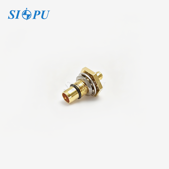
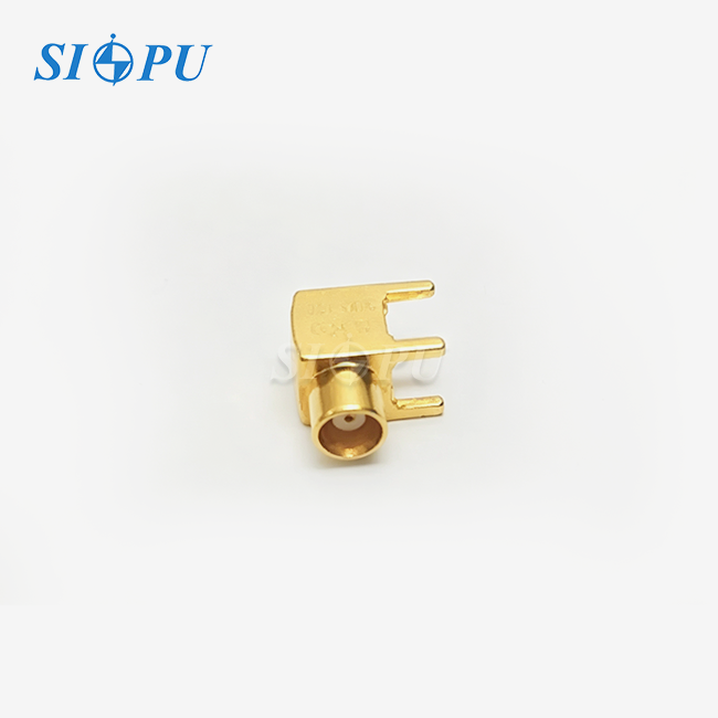
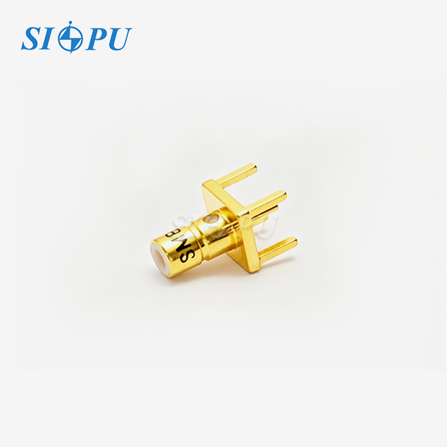
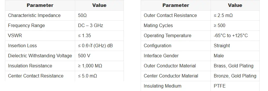
Reducing signal loss starts at the connector level. A SSMB male straight PCB mount connector delivers a 50 Ω impedance path from DC to 3 GHz, with VSWR ≤ 1.35 and insertion loss ≤ 0.6√f dB—two figures that directly govern signal integrity on dense RF boards. Its straight solder-mount configuration creates a continuous, low-discontinuity signal path, while a gold-plated bronze body and PTFE dielectric keep contact resistance and dielectric losses tightly controlled. For RF design teams working under board-space pressure, this connector type offers a measurable, repeatable advantage.
Understanding Signal Loss in SSMB Male Straight PCB Mount Connectors
Signal loss isn't caused by just one thing. It builds up across shapes, materials, and the quality of the interface. If you know where the loss is coming from, you can fix it before the plan is made.
Where Material Properties Drive Loss
On a good SSMB male straight PCB mount connector, the outer and middle wires are made of gold-plated bronze. Gold treatment keeps the contact resistance at ≤ 5.0 mΩ (middle) and ≤ 2.5 mΩ (outer). This is because it lowers the bulk resistivity and stops oxidation. The PTFE dielectric has a loss tangent close to 0.0002, which means it doesn't absorb much in the DC–3 GHz band. Cheaper contacts made of tin or bare copper tarnish over time, which makes ohmic loss much worse in the first year of use.
How Impedance Mismatch Creates Reflection Loss
A 50 Ω system sends energy back into the circuit when it comes across a break in the resistance. There could be a difference in resistance of as little as 2–3 Ω in a link that doesn't meet size standards. This is more than enough to make the VSWR more than 1.5 and the return loss less than 14 dB. A CMM test confirmed that the SSMB PCB mount connector's body is precisely CNC-machined, which keeps the impedance in the right range to achieve VSWR ≤ 1.35 across the rated band.
How Frequency Range Affects Attenuation
Any coaxial connection has insertion loss that goes up or down with frequency. This relationship can be measured with the formula ≤ 0.6√f (GHz) dB. Insertion loss stays below 0.6 dB at 1 GHz and below 1.04 dB at 3 GHz. That's not too high of a number for most RF module, GPS, and test instrument uses. Engineers can plan for total path loss across cables, connectors, and board traces without buying too many expensive parts if they know about this scaling.
Comparing SSMB to Other PCB Mount Connectors for Signal Loss Reduction
Choosing the right connector interface means comparing frequency capability, footprint, and assembly method side by side. SSMB sits in a well-defined position on that matrix.
SSMB vs. SMB: Size and Density Trade-Off
SMB connectors can handle DC to 4 GHz, but they take up three times as much space on the board as an SSMB. When you switch to SSMB, you save a lot of room on a high-density RF module where ten or more links share a single board. Since they both use snap-on connection, the speed of setup is about the same. The SSMB male PCB connector type is better if your design works below 3 GHz and board density is important.
SSMB vs. SMA: Frequency vs. Integration Density
SMA connectors can handle up to 18 GHz and have threaded locking, which makes them good for work like panel mounting and cable assembly. SMA, on the other hand, needs a torque wrench to connect consistently and takes up a lot of PCB edge space. The SSMB PCB solder-mount connection can be snapped on without any tools, can be used for automatic assembly, and keeps the board's size small. For uses that can't go above 3 GHz, like cell phone modules and GPS stations, SMA adds size and cost without improving the signal in any useful way.
Straight vs. Right-Angle: Orientation and Loss
A straight male SSMB connection sends the signal straight off the board, with no bends in the line. This straight shape has fewer breaks than a right-angle version, where an internal 90° shift causes a small but detectable change in resistance. At frequencies above 1.5 GHz, the straight configuration always has lower insertion loss and better return loss than a right-angle unit of the same type used in precision signal-chain designs.
Proven Techniques to Reduce Signal Loss with SSMB Male Straight PCB Mount Connectors
It's not enough to just have good connection specs. How well those specs are installed and how well they are maintained over time decide how long those specs last.
Here are the most important things that must be done to keep signals safe at the plug interface:
As per IPC/EIA J-STD-002, control the soldering process by reflow or wave soldering the SSMB PCB mount connector. A full wetting angle at the solder pad makes sure that there is low contact resistance and that the structure is stable. Joints that are cold or bridged make the contact resistance higher and add points for EMI to enter.
- Soldering process control: Reflow or wave solder the SSMB PCB mount connector per IPC/EIA J-STD-002. A full wetting angle at the solder pad ensures low contact resistance and mechanical stability. Cold or bridged joints raise contact resistance and introduce EMI entry points.
- PCB pad design: Size the ground pads to match the connector's outer conductor footprint exactly. Oversized or undersized pads shift the local impedance at the launch point, degrading return loss in the upper portion of the DC–3 GHz band.
- Plating verification: Use XRF (X-ray fluorescence) testing to confirm gold plating thickness. Thinner plating wears through faster, exposing the nickel barrier layer. For units exported to the EU, note that gold-over-nickel plating must comply with REACH nickel release limits (≤ 0.5 µg/cm²/week) where skin contact or moisture exposure is possible.
- Retention force checks: For high-vibration environments, verify snap-on retention force during incoming inspection. The SSMB snap-on coupling is tested to ≥ 500 mating cycles; if the application involves constant reconnection, schedule periodic retention force audits.
All of these steps keep the observed performance in line with the connector's paper specs from the time it is first put together until it is no longer useful. If you specify the right connector but don't install it properly, it won't give you the VSWR and insertion loss numbers that your design needs.
How to Evaluate and Source the Best SSMB Male Straight PCB Mount Connectors
Procurement decisions for RF connectors involve more than price per unit. Supply continuity, certification status, and sample lead time all affect total project risk.
Key Selection Criteria for RF Module OEM Teams
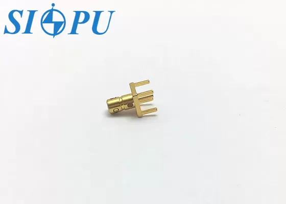
When evaluating an SSMB male straight PCB mount connector supplier, confirm that each product undergoes 100% VNA testing for return loss and insertion loss across DC–3 GHz. Dimensional accuracy should be verified by CMM, and solderability tested per J-STD-002. Suppliers holding ISO 9001 certification provide documented process control, which directly supports consistency across production batches—the single largest concern for high-volume module assemblers.
Sample and Lead Time Considerations
For teams operating on a 1–3 month qualification cycle, sample turnaround is a gating factor. A supplier with standard SSMB PCB solder-mount connectors in stock can typically dispatch samples within 72 hours. Custom pin configurations or non-standard plating specifications require a dedicated production run; confirm the quoted lead time against your qualification schedule before committing to a design revision that depends on a non-stock part.
Compliance and Export Classification
SSMB connectors operating DC–3 GHz generally fall under EAR99 for US export. The governing interface standard is IEC 61169-10, combined with internal pin structure protocols. Do not conflate this with IEC 61754, which covers fiber-optic interfaces and carries no relevance to RF coaxial products. For EU shipments, actively disclose nickel sensitization risk for gold-over-nickel-plated products per REACH CLP requirements.
Future-Proofing Your Signal Integrity: Trends and Innovations in SSMB Connectors
As more 5G sub-6 GHz modules and IoT edge devices come out, there will be even more pressure to fit more RF channels onto smaller boards. As a result, connector makers are making their products with better mechanical standards, smaller dielectric sections, and shielding built in at the board level. Early research from a number of major manufacturers points to SSMB-class connectors that have passive impedance monitoring built into the housing. This would allow for trending of return loss while the connectors are in use without the need for external test equipment. If procurement teams are looking at multi-year supply agreements, picking a supplier that can do active product development lowers the chance that connectors will become obsolete in the middle of a program.
Conclusion
Signal loss in a PCB RF line can be controlled if the connectors are chosen, installed, and sourced correctly. The SSMB male straight PCB mount connector fixes the three main types of loss: material resistance, impedance mismatch, and dielectric absorption. It does this with gold-plated bronze contacts, PTFE insulation, and CNC-machined accuracy in size. Its straight solder-mount design keeps the signal path clear, and its small size lets you make board layouts with a lot of components. Understanding these factors during the design phase, along with focused buying and assembly methods, leads to systems that work as planned from the pilot stage through production.
FAQ
1. What is the maximum frequency for an SSMB male straight PCB mount connector?
DC to 3 GHz is the frequency range that standard SSMB solder-mount connectors are licensed to work with. Some specialized high-grade versions can go up to 4 GHz, but before finishing a design, it's a good idea to compare the document specs to the frequency of your application.
2. What is the difference between SSMB and SMB connectors?
SSMB is a very small version of the SMB interface, about one-third the size of the body of the SMB interface. Snap-on connection is used on both. In high-density setups where board space is limited, the SSMB PCB connector is better, while the SMB is better for uses that need a slightly larger and more mechanically strong interface.
3. Can an SSMB connector operate in a 75 Ω system?
No. The SSMB connector is designed for a 50 Ω impedance system. Using it in a 75 Ω system creates an impedance mismatch, which raises VSWR and increases reflection loss across the whole operating band. Choose the impedance interface that is right for your system architecture.
4. How does solder-mount design affect EMI performance?
When you attach the outer conductor to the PCB, it is directly connected to the ground plane. This makes it much harder for EMI to enter and leave the connector. This is a big benefit over snap-on cable connectors in RF front-end designs that need to be quiet.
5. What operating temperature range does this connector support?
The SSMB male straight PCB mount connector works in temperatures ranging from -65 °C to +125 °C, which means it can handle most industry and military thermal conditions without losing performance.
Get Your SSMB Male Straight PCB Mount Connector Quote from SIPU
Since 1998, SIPU has been making high-precision RF connectors. Each SSMB male straight PCB mount connector is checked by 100% VNA testing and is made in a quality system that is ISO 9001 approved. As a direct SSMB male straight PCB mount connector maker, we have a lot of stock, can send out samples within 72 hours, and can work with OEMs and ODMs to make unique pin configurations or plating specs. To get a sample, datasheet, or bulk price, email our engineering team at info@sipu-rf.com or go to sipuconn.com.
References
-
IEC 61169-10:2022 — Radio-Frequency Connectors: Part 10 — Sectional Specification for Series SSMB rf coaxial connectors. International Electrotechnical Commission, 2022.
-
IPC/EIA J-STD-002E — Solderability Tests for Component Leads, Terminations, Lugs, Terminals, and Wires. IPC, 2017.
-
Pozar, D. M. — Microwave Engineering, 4th ed. Wiley, 2011.
-
MIL-STD-348B — Radio Frequency Connector Interfaces for MIL-DTL-3643, MIL-DTL-3650, MIL-DTL-3655, and MIL-DTL-25516 Connectors. U.S. Department of Defense, 2011.
-
European Chemicals Agency (ECHA) — REACH Regulation: Nickel Release Restrictions Under Annex XVII, Entry 27. ECHA, 2023.
-
Wadell, B. C. — Transmission Line Design Handbook. Artech House, 1991.
Contact us directly for customized solutions, quotations and long-term strategic cooperation.