- English
- French
- German
- Portuguese
- Spanish
- Russian
- Japanese
- Korean
- Arabic
- Greek
- German
- Turkish
- Italian
- Danish
- Romanian
- Indonesian
- Czech
- Afrikaans
- Swedish
- Polish
- Basque
- Catalan
- Esperanto
- Hindi
- Lao
- Albanian
- Amharic
- Armenian
- Azerbaijani
- Belarusian
- Bengali
- Bosnian
- Bulgarian
- Cebuano
- Chichewa
- Corsican
- Croatian
- Dutch
- Estonian
- Filipino
- Finnish
- Frisian
- Galician
- Georgian
- Gujarati
- Haitian
- Hausa
- Hawaiian
- Hebrew
- Hmong
- Hungarian
- Icelandic
- Igbo
- Javanese
- Kannada
- Kazakh
- Khmer
- Kurdish
- Kyrgyz
- Latin
- Latvian
- Lithuanian
- Luxembou..
- Macedonian
- Malagasy
- Malay
- Malayalam
- Maltese
- Maori
- Marathi
- Mongolian
- Burmese
- Nepali
- Norwegian
- Pashto
- Persian
- Punjabi
- Serbian
- Sesotho
- Sinhala
- Slovak
- Slovenian
- Somali
- Samoan
- Scots Gaelic
- Shona
- Sindhi
- Sundanese
- Swahili
- Tajik
- Tamil
- Telugu
- Thai
- Ukrainian
- Urdu
- Uzbek
- Vietnamese
- Welsh
- Xhosa
- Yiddish
- Yoruba
- Zulu
What Makes BMA Male Thread Mount Receptacle Different from SMA?
A BMA male thread mount receptacle differs from SMA mainly in how it mates. SMA relies on a threaded coupling nut that a technician turns by hand or with a wrench. The BMA male thread mount receptacle uses a push-on, slide-in interface, so a module seats against the chassis without rotation, while a threaded body and nut lock the receptacle itself to the panel. Both families use 50 Ω impedance, yet their dimensions, tolerances, and mating hardware differ. In this guide, I explain those differences and show what radar, test, and modular system teams should verify before approving a part.
BMA Male Thread Mount Receptacle vs. SMA: Start with the Fundamental Difference
What Is a BMA Male Thread Mount Receptacle?
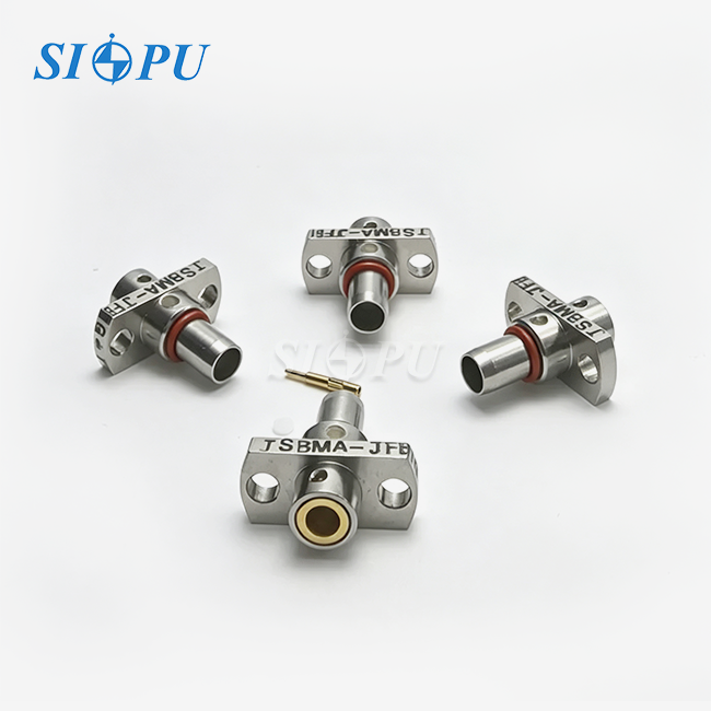
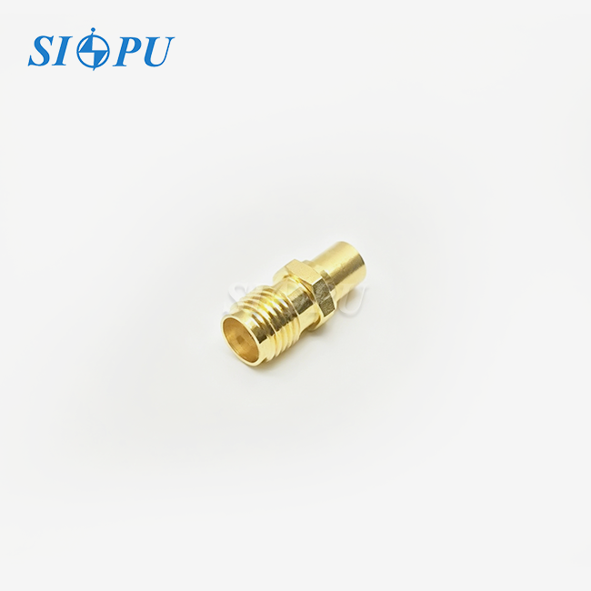
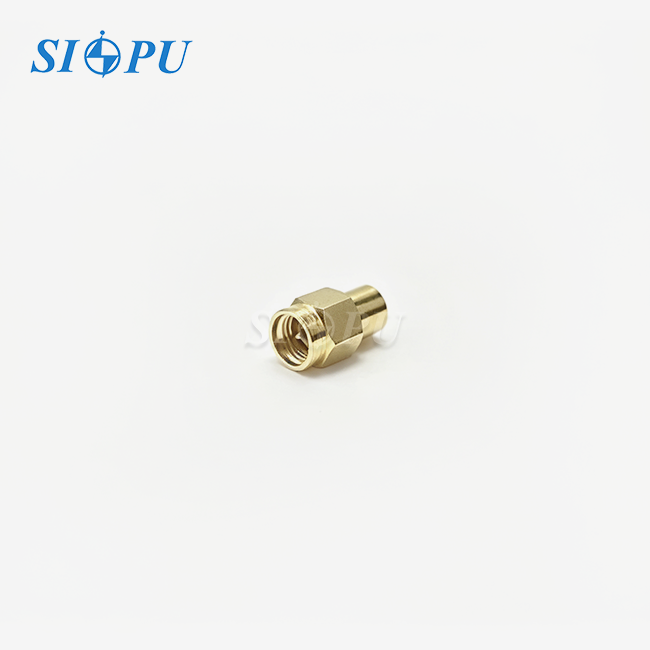
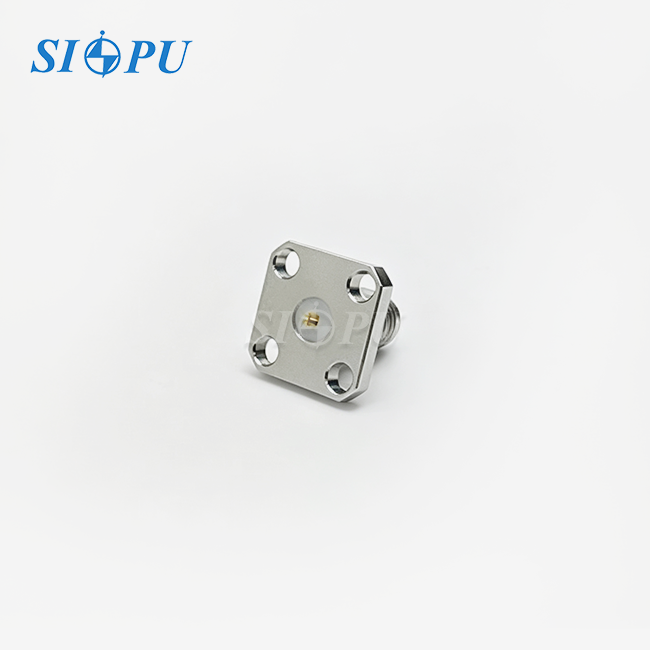
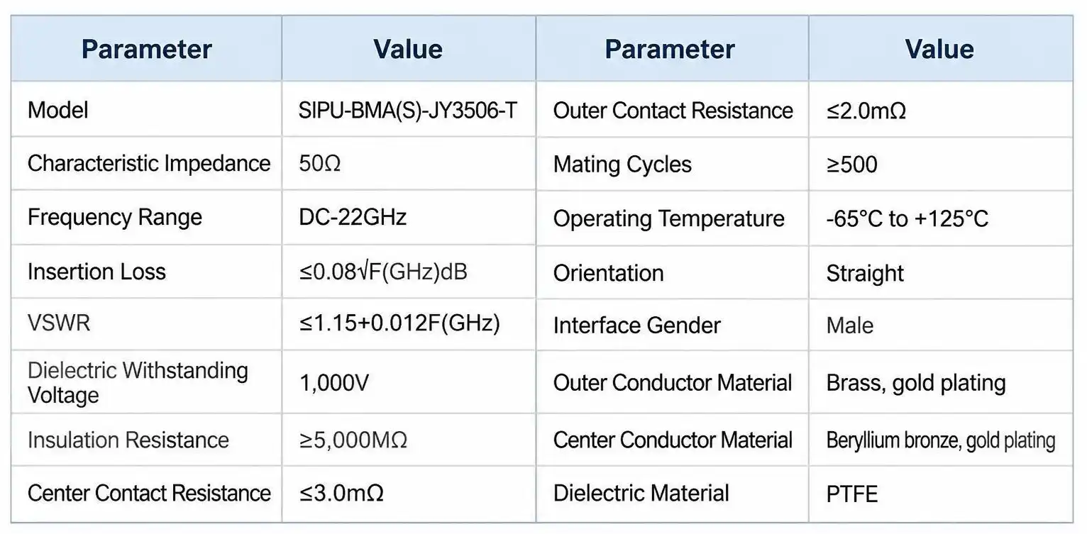
A BMA male thread mount receptacle is a coaxial connector that is mounted on a panel and has a male BMA interface. The shapes of the BMA blind-mate interface can be seen in Figure 321 of MIL-STD-348B. The male center contact fits into a matching part inside the module. A threaded body then goes through the chassis hole and is held in place by a nut. The thread only holds the plug to the panel; it doesn't connect the RF interface. This is our SIPU-BMA(S)-JY3506-T. It has a straight, push-on design, 50 Ω impedance, and a range from DC to 22 GHz. The construction is finished with a gold-plated brass body, a gold-plated beryllium bronze center contact, and a PTFE dielectric.
What Is an SMA Connector?
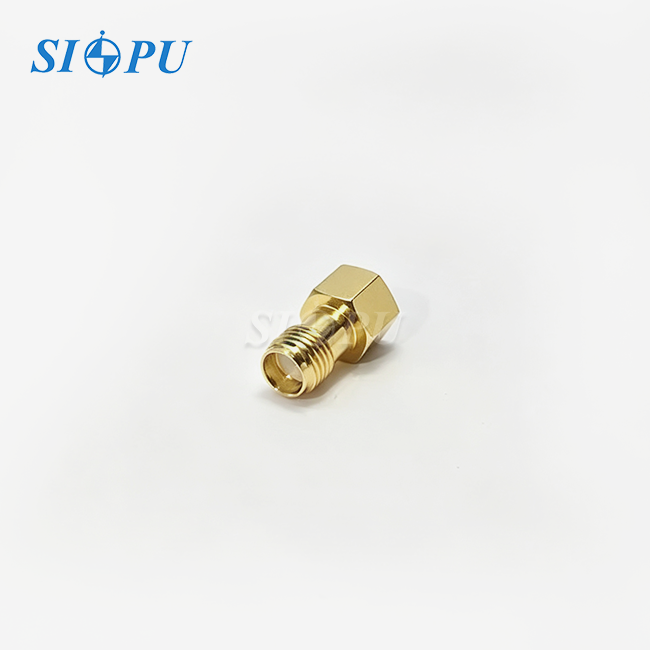
SMA is a 50 Ω coaxial connector that fits together with a threaded coupling nut. The center pin is lined up, the nut is turned on by hand, and it is tightened to a certain torque. For many brass SMA connectors, this torque is about 5 in-lb. The nut holds the joint together, so it stays firm even when it's being moved. Lab cables, antennas, and test equipment all use SMA, and many suppliers carry a wide range of its cables and adapters. Most of the time, standard SMA is limited to 18 GHz, but precision versions can go higher. SMA is a good choice wherever a port is accessible because it is easy to use and widely used.
Why the Two Connectors Are Not Direct Substitutes
It's not enough for two connections to have the same 50 Ω resistance for them to work together. They don't fit together perfectly because a BMA slide-on interface isn't the same size and doesn't have a connection nut on the side that fits together. When you switch them, the panel cutout, back space, hardware that fits, and often the module housing are all different. A lot of BMA catalogs say the highest frequency is 18 GHz, but our BMA male thread mount receptacle says it can handle 22 GHz, so I suggest that you compare any replacement with recorded data from a paired pair. Before you accept a change, make sure that the electrical, mechanical, and application all work well together.
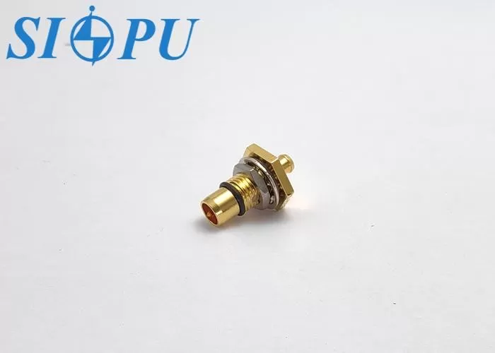
BMA and SMA Mating Mechanisms: Blind-Mate Alignment vs. Threaded Coupling
How a BMA Male Thread Mount Receptacle Works?
A module moves along tracks in a rack to reach the backplane. The BMA interface connects by pushing it in one direction, so the center contact and outer conductor touch without having to turn a nut. A well-thought-out BMA male thread mount receptacle holds the body to the chassis, and float in the matching hardware lets it handle small alignment errors. Because float limits are different for each design, you should get the axial and radial values for your specific part number and compare them to your tolerance stack. Our SIPU-BMA(S)-JY3506-T's push-on design lets you use this slide-in method, and its nut-locking structure keeps the body in place when vibrations reach the cabinet.
How SMA Threaded Mating Works
Align the center pin, turn the coupling nut by hand, and tighten to torque. That's all there is to it. When someone can see and reach the port, SMA works well because the thread locks the joint and keeps the contact pressure steady. Access is what it costs. A wrench needs space to swing, and turning the nut or cable twists the whole thing. Inside a thick cabinet, wires come out of the front, and switching modules requires several connections. SMA also needs consistent torque because joints that are too loose move around and joints that are too tight wear out the threads. It takes longer to do these things on a factory line or in the field.
Practical Impact on Equipment Design
The mate style shapes the whole enclosure. SMA designs put wires on sides that are easy to reach and make room for tools. The RF path can go through the backplane thanks to a BMA male thread mount receptacle. This means that a worker can pull out a module and put in a new one without having to turn a coupling nut. This plan works well for radar and electronic countermeasure cabinets, phased-array racks, microwave switch matrices, and test tools that have a lot of ports close together. It's still possible to use SMA on benches, antenna ports, and prototypes where cables are often reconnected. Before you start comparing electrical families, you should first decide if your architecture needs fast, repeatable module insertion. If it does, you can usually point to one family.
BMA Male Thread Mount Receptacle vs. SMA: Key Technical Differences
Frequency Range and High-Frequency Suitability
Frequency range is where you should focus your attention. Many standard SMA specifications state a limit of 18 GHz, and the same is true for many BMA catalogs. The SIPU-BMA(S)-JY3506-T can work from DC to 22 GHz at 50 Ω. Radar and electronic countermeasure teams are right to ask for measured evidence since 22 GHz is above the normal BMA catalog limit. I think you should look over the VSWR curve that was taken on a mated pair across the whole band, using the fixture and calibration method that was explained. The points where your method works aren't really shown by a single maximum-frequency claim.
VSWR, Insertion Loss, and Repeatability
The SIPU-BMA(S)-JY3506-T has a VSWR of ≤1.15+0.012F and an insertion loss of ≤0.08√F dB, where F is the frequency in GHz. Based on the math, the VSWR limit is around 1.37 at 18 GHz and 1.41 at 22 GHz. The insertion loss limit is around 0.34 dB and 0.38 dB. The center contact resistance is ≤3.0 mΩ and the outer contact resistance is ≤2.0 mΩ. It is stated that the contacts can be mated up to 500 times. Since blind-mate modules are often switched out, repeatability is important. Ask any provider how it tested resistance after cycling and under what conditions.
Operating Temperature and Environmental Resistance
Between -65℃ and +125℃, this BMA male thread mount receptacle works. The PTFE insulator stays in shape, and the gold finish on the brass body and beryllium bronze center contact keeps them from oxidizing. The building lasts a long time, is resistant to vibrations, and is waterproof. The electrical isolation must be able to withstand a voltage of 1,000 V and an insulation resistance of at least 5,000 MΩ. Since each program has its own shock and vibration profiles, I think you should ask for a report that follows the random vibration method in MIL-STD-202 and matches your acceptance test. Waterproof claims also need to be backed up by a test condition, so make sure you ask for one before the design freeze.
Mechanical and Installation Differences Between BMA and SMA
BMA Male Thread Mount Receptacle Dimensions
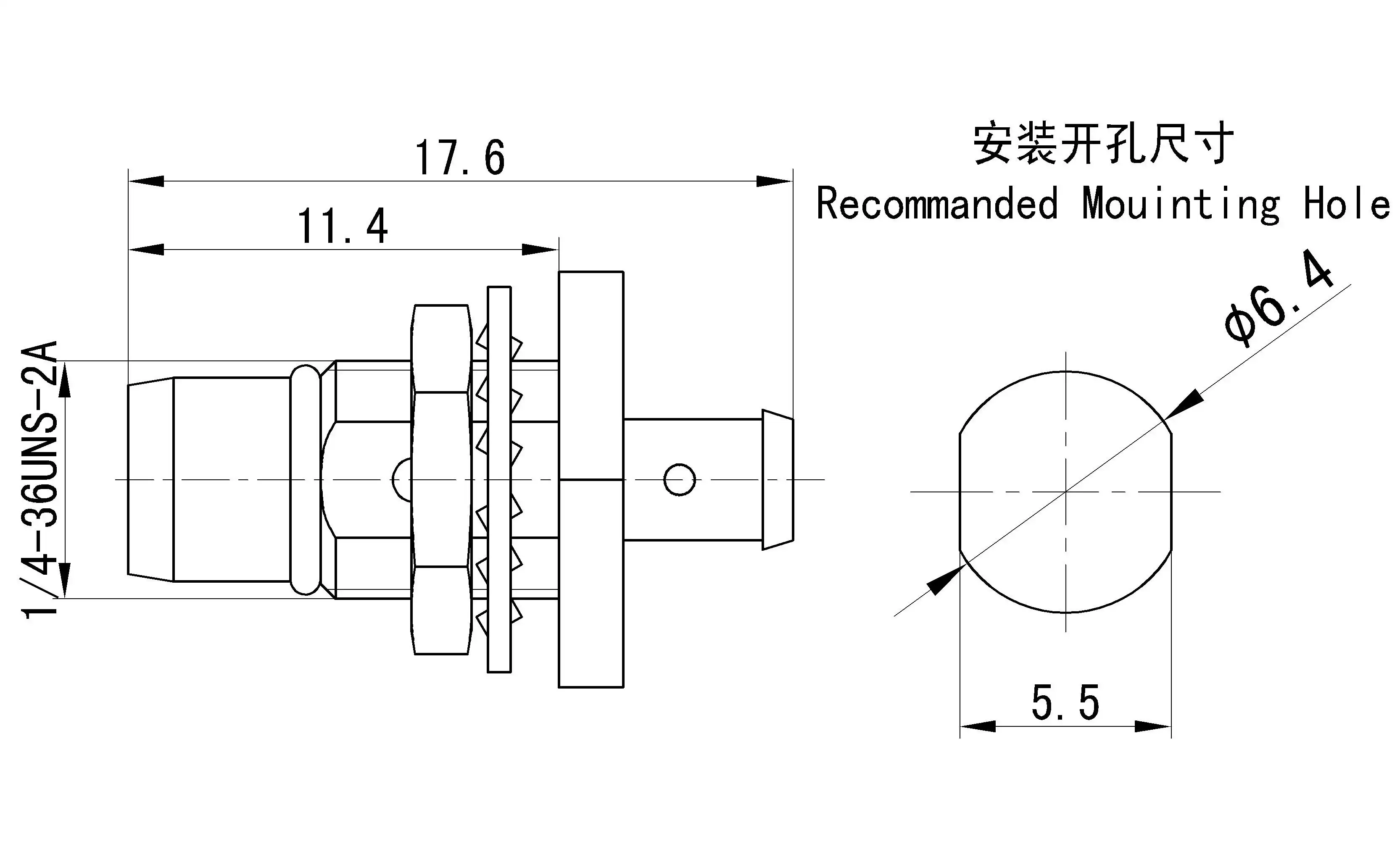
Before a cabinet hole is cut for a BMA male thread mount receptacle, the plan needs to be checked. Check the mounting thread size, the shape of the panel cutout, the body length, the contact position, the range of panel thicknesses, and the space behind the plate in the back. Check to see how far the center contact is from the face of the panel. This number determines the mating travel and lift. We give you mechanical drawings and help with installation, and our engineers can check your drawing of the cabinet opening against the part before you send it off. Always work from the most recent version of the drawing, since the part you get may be different from an older version.
Mounting and Installation Checklist
Before you use a BMA male thread mount receptacle, make sure the panel is conductive and the mounting surface is clean. This is because the threaded body connects to the panel through that contact. Place the plug into the hole, attach the nut, and tighten it to the torque shown on the drawing. The nut-locking structure protects the body from shaking and provides a low-impedance path to the chassis. Compare the thread length to the thickness of the panel. Then put in a module and make sure it fits without putting any weight on the sides. To make it easier to find, write down the lot numbers and torque values. For SMA installations, wrench clearance is added to this list. With a BMA layout, torque work is only needed for the one-time panel installation and not for every module swap.
Mating Connector Compatibility
The plug is only half of the contact. Make sure that the mating part inside the module has the opposite gender and the right BMA interface, and that its float travel is within your tolerance stack. It's helpful that our part works with CXN3506 cable when the module-side assembly needs to use that cable. Keying and mating movement should show up on the image of the interface. Compare the sizes to MIL-STD-348B, Figure 321, which shows how the BMA interface is set up, to make sure that parts from different sources can still fit together. A mistake here costs more than any difference in price between suppliers.
How to Choose the Right BMA Male Thread Mount Receptacle
Define the System Requirements Before Comparing Suppliers
Before you ask for quotes, write down the frequency range, VSWR limit, power level, temperature range, vibration profile, number of union cycles, and amount. Add the business side as well. During the life of a radar or test system, the steps usually go from reviewing the interface to validating samples to volume over a period of several months. The steps are then repeated. With a requirement sheet, all suppliers can answer the same questions, which means that all quotes for BMA male thread mount receptacle are the same. It also gives the RF expert and the assembly boss a single document to sign off on.
Review the Supplier's Technical Documentation
For the same part number and revision, look at the datasheets, drawings, test results, and quality papers side by side. A VSWR claim that doesn't include frequency points, a description of the fixture, and a way for testing doesn't hold much weight. For a 22 GHz BMA male thread mount receptacle, I think you should ask for the measured VSWR curve and any documentation of vibration tests. Send us your frequency points and sound profile, and our researchers will look over the data we have collected and get back to you. RoHS documents and material declarations should be kept in the same package. SIPU follows MIL, GJB, and IEC standards when making its products. It also follows ISO 9001 and is in line with CE and RoHS regulations.
Validate Through Samples and Testing
You should check samples on your own before approving the whole order. These checks should include how well they fit in the cabinet cutout, the VSWR on a mated pair, the contact resistance after many cycles, and a vibration run with the RF path being watched. As part of our quality control process, we check each unit's thread accuracy and pin alignment, as well as its dielectric's ability to withstand voltage and insulation resistance. We also check each batch's plating thickness and adhesion. Because VSWR and insertion loss depend on how the structure is built, your example test shows that they are correct in your own assembly. We use CNC machines and RF testing tools to make every BMA male thread mount receptacle, and we back prototypes all the way through production.
Conclusion
An SMA connector and a BMA male thread mount receptacle both have an impedance of 50 Ω, but they are installed, mated, and sized differently. SMA uses a threaded coupling nut and works well in labs, prototypes, and ports that are easy to get to. The BMA interface slides in along the axis, and the threaded body and nut secure the receptacle to a conductive frame. This works for modules that need to be changed without having to turn a coupling nut. The SIPU-BMA(S)-JY3506-T is defined from DC to 22 GHz, which is higher than the 18 GHz limit that is common in BMA catalogs. To make sure it works, it's best to test the VSWR data on a paired pair. The evaluation is finished with mechanical drawings, evidence of vibration, float tolerance, and compatibility between mating parts. Instead of looking at the name of the connector, it's best to choose based on its specifications and how well it has been tested.
FAQ
1. Is a BMA male thread mount receptacle interchangeable with an SMA connector?
Not at all. Even though both use 50 Ω impedance, the connecting interface, measurements, and hardware are different, so a swap needs to be looked over, redesigned, and tested to make sure it works.
2. What is the main advantage of a BMA receptacle over SMA?
Blind-mate insertion. The modules slide into the backplane without having to turn a coupling nut. This makes it faster to replace modules in cabinets with a lot of them.
3. Does "thread mount" mean that the BMA connector mates through threads?
No. The chassis is held together by the thread and nut, and the RF interface connects by pushing it on.
4. Are BMA receptacles suitable for high-frequency applications?
The range of our SIPU-BMA(S)-JY3506-T is from DC to 22 GHz. Many BMA catalogs stop at 18 GHz, so check the VSWR on a paired pair.
5. What information is needed to request a BMA receptacle quotation?
6. Send information about the frequency range, impedance, mounting dimensions, operating environment, quantity, and delivery needs.
7. Can a BMA male threaded receptacle be customized?
Yes, SIPU can support unique electrical performance, materials, and mechanical design from the pilot to the mass production level.
Request a BMA Male Thread Mount Receptacle Recommendation
SIPU wants to see your drawings and needs for a BMA male thread mount receptacle. As an ISO 9001-certified BMA male thread mount receptacle manufacturer, we can answer your questions in 12 hours, ship standard connectors from stock in 72 hours, and provide custom support from the prototype to the mass production level. Our North American partner, JNP Supplies in Seattle, is in charge of local planning. Send an email to info@sipu-rf.com with your frequency, mounting dimensions, environment, and quantity. You can also find out more at sipuconn.com.
References
1. MIL-STD-348B, Radio Frequency Connector Interfaces for MIL-PRF-39012 Connectors, 2013
2. MIL-STD-202H, Test Method Standard: Electronic and Electrical Component Parts, 2015
3. IEC 61169-1, Radio-frequency connectors – Part 1: Generic specification, 2013
4. IEEE Std 287, IEEE Standard for Precision Coaxial Connectors (DC to 110 GHz), 2007
5. Pozar, D. M., Microwave Engineering, 4th Edition, 2011
6. GJB 5246-2004, Interface Dimensions of rf coaxial connectors, 2004
Contact us directly for customized solutions, quotations and long-term strategic cooperation.