- English
- French
- German
- Portuguese
- Spanish
- Russian
- Japanese
- Korean
- Arabic
- Greek
- German
- Turkish
- Italian
- Danish
- Romanian
- Indonesian
- Czech
- Afrikaans
- Swedish
- Polish
- Basque
- Catalan
- Esperanto
- Hindi
- Lao
- Albanian
- Amharic
- Armenian
- Azerbaijani
- Belarusian
- Bengali
- Bosnian
- Bulgarian
- Cebuano
- Chichewa
- Corsican
- Croatian
- Dutch
- Estonian
- Filipino
- Finnish
- Frisian
- Galician
- Georgian
- Gujarati
- Haitian
- Hausa
- Hawaiian
- Hebrew
- Hmong
- Hungarian
- Icelandic
- Igbo
- Javanese
- Kannada
- Kazakh
- Khmer
- Kurdish
- Kyrgyz
- Latin
- Latvian
- Lithuanian
- Luxembou..
- Macedonian
- Malagasy
- Malay
- Malayalam
- Maltese
- Maori
- Marathi
- Mongolian
- Burmese
- Nepali
- Norwegian
- Pashto
- Persian
- Punjabi
- Serbian
- Sesotho
- Sinhala
- Slovak
- Slovenian
- Somali
- Samoan
- Scots Gaelic
- Shona
- Sindhi
- Sundanese
- Swahili
- Tajik
- Tamil
- Telugu
- Thai
- Ukrainian
- Urdu
- Uzbek
- Vietnamese
- Welsh
- Xhosa
- Yiddish
- Yoruba
- Zulu
How MCX Female PCB Mount 4-Pin Connector Improves Solder Strength
An MCX female PCB mount 4-pin connector improves solder strength by sharing mechanical load across four through-hole pins instead of one small joint or surface pad. Each pin passes through the board and forms its own solder fillet, so insertion force, cable pull, and vibration divide among four anchors. On the SIPU-MCX-KWHD1, this four-pin through-hole design offers more joint strength than surface-mount options and suits vibration-prone products. Strong joints also protect the RF path, which this model specifies at VSWR ≤1.4 from DC to 6 GHz. Below, I explain the design logic, common failure causes, and the checks buyers should make before ordering.
Why Solder Strength Matters for an MCX Female PCB Mount 4-Pin Connector
Solder Joints Carry Mechanical and RF Load
On an RF board, a solder link does two things. It holds the connector to the PCB and finishes the ground path that the return current comes along. Changes happen in that path when a joint cracks or a pad lifts. You may see signals that come and go, higher RF loss, or noise that only shows up when the device is vibrating. The same joints are strained by thermal cycling, mating cables over and over, and tight routing. If one of the four pins on an MCX female PCB mount 4-pin connector fails on a GNSS module, car T-Box, or drone video link, the unit may need to be sent back or the line may stop. When I think about glue strength, I don't just think about it in terms of mechanics.
How Four Through-Hole Pins Share the Load
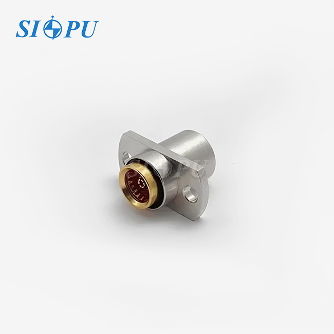
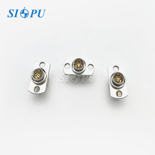
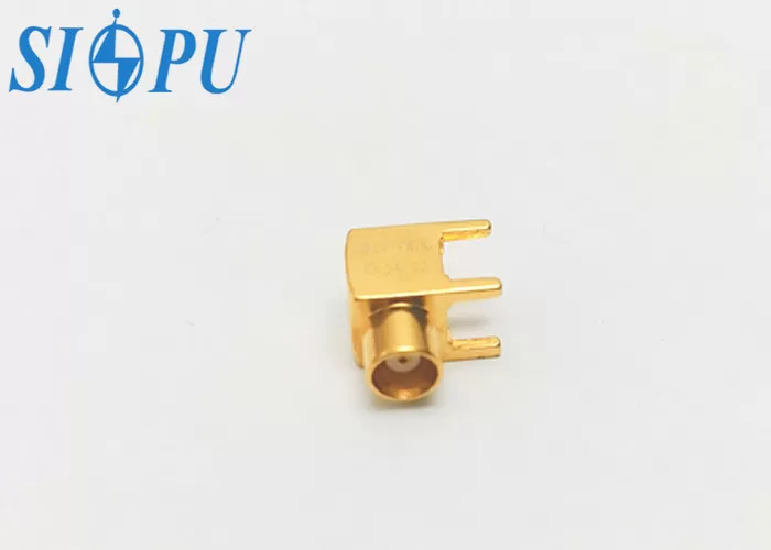
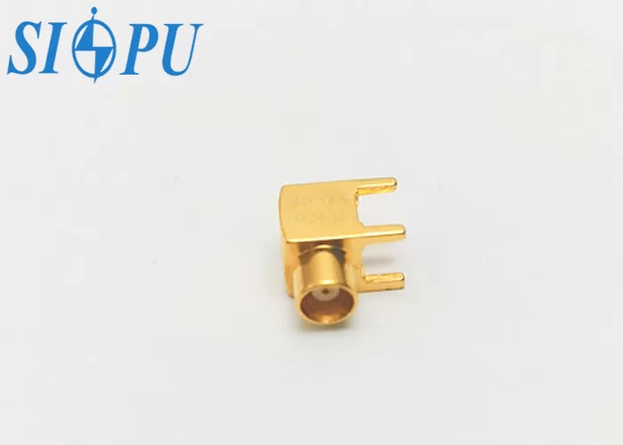
There are four through-hole pins on the SIPU-MCX-KWHD1, which is an MCX female PCB mount 4-pin connector. Each pin has its own solder fillet and sits in a plated hole. This way, the force from inserting, removing, and vibration is spread out over four anchor points instead of just one. In the SIPU product info, it says that this setup gives a stronger solder joint than surface-mount choices, with better resistance to shear and torque. But four pins can't fix a pad that isn't made well. The end result is still determined by the hole size, the annular ring, and the soldering process. A balanced footprint keeps the pull from focusing on a single corner.
What "4-Pin" Means on the SIPU Model
"4-pin" does not always mean the same thing in MCX. It can be used by some providers for four ground connections, four solder tabs, or a different number of contacts. It refers to the SIPU-MCX-KWHD1's right-angle body with four through-hole pins, a female interface, and an impedance of 50 Ω. Before releasing the layout, I always tell people to check the datasheet, pinout, and 2D/3D drawings against their own PCB footprint. If you ask, SIPU will send you these papers along with VSWR and insertion loss data. This one check stops footprint mismatches that would happen after boards come back from being put together.
Main Causes of Weak Solder Joints and the Effect of Mounting Method
Pad, Hole, and Process Errors Behind Weak Joints
An easy mistake in the layout or process can cause a joint to become weak. Too few copper is present for a good fillet because the pads are too small, the plated holes are the wrong diameters, the annular rings are too thin, and the ground planes are too far apart. The next group of flaws on the line are caused by cold joints, poor wetting, too much heat, solder bridges, and flux residue. The PTFE dielectric can also be damaged by too much heat, so SIPU suggests a managed temperature profile. IPC-A-610 talks about how inspectors judge solder joints, and IPC-2221B talks about how to create a general printed board. If you compare the source drawing to the footprint of any MCX female PCB mount 4-pin connector before the first build, you can find many of these issues early on.
Mechanical and Environmental Stress Sources
Even a good joint can break when outside forces put too much stress on it. A thick coaxial cable, a tight bend near the connector, or a lot of service work can pull the board through the body of the connector. Since the force works away from the pads, side-entry right-angle cables give you more traction. Over time, vibration in vehicles and drones makes parts wear out, and humidity or corrosion can damage surfaces that aren't properly coated. The SIPU model works in a wide temperature range, from -65°C to +125°C. However, the wire weight should still be supported by the container and clamps. Solder can't handle that load by itself.
Through-Hole, Surface-Mount, and Right-Angle Compared
Through-hole connectors can usually handle pull-out and side loads better, which makes them good for rough handling and frequent mating. They need to drill and have more room on the board. Surface-mount parts allow for automatic assembly and small plans, but the design of the pads, the amount of solder used, and process control are very important. Right-angle connectors run the cable parallel to the board and save vertical space. Straight connectors make alignment easier but raise the enclosure. An MCX female PCB mount 4-pin connector in the right-angle, through-hole format works well for high-density modules that are likely to vibrate. Before you make a decision, look at the ground vias, space, and wire access in CAD.
MCX Female PCB Mount 4-Pin Connector Specifications Buyers Should Verify
Electrical and Mechanical Parameters to Confirm
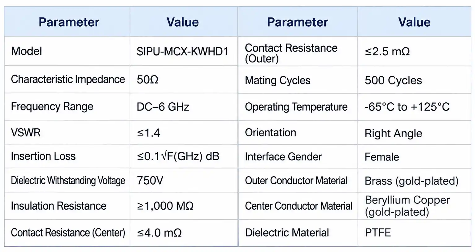
Here are the first things I look at on the datasheet for an MCX female PCB mount 4-pin connector:
- RF performance: The connector has a characteristic impedance of 50 Ω, works with frequencies from DC to 6 GHz, and has a VSWR of 1.4 and an insertion loss of 0.1√F(GHz) dB. Since insertion loss rises with frequency, engineers can compare these numbers to their product's link budget. The numbers cover GNSS, 4G, and Wi-Fi bands.
- Electrical safety and contact values: The dielectric can handle 750 V of voltage, has an insulation resistance of at least 1,000 MΩ, and has a contact resistance of ≤4.0 mΩ in the middle and ≤2.5 mΩ on the outside. It's important to have low outer contact resistance because the ground return current goes through the joints along that path.
- Mechanical data: This is a right-angle female MCX interface with four through-hole pins. It can be mated 500 times and has a snap-on retention force of about 10 N (2.3 lbs). Before releasing the layout and again before the first production build, check the mechanical drawing to make sure the mounting height, PCB thickness, and hole pattern are correct.
Materials, Plating, and Compliance
Gold-plated brass makes up the outer conductor. Gold-plated beryllium copper makes up the center contact, and PTFE makes up the dielectric. Asking about plating thickness and adhesion results will help you figure out how well the plating works and how long the contacts last. Check what each supplier tests each batch of MCX female PCB mount 4-pin connectors when you compare offers. Each batch of products made by SIPU is checked for RoHS compliance, plating thickness, adhesion, dielectric withstanding voltage, and insulation resistance. The company has ISO 9001 and CE certificates. Per-batch RoHS reports and steady plating reduce lot-to-lot differences that cause poor wetting. EU RoHS requirements follow Directive 2011/65/EU.
MCX Versus SMA and MMCX Alternatives
SMA connectors use a threaded coupling, which gives a firmer mate and suits laboratory and demanding RF work, but they take more space. MCX uses a snap-on interface that mates quickly in a smaller body, and the SIPU model is rated for 500 mating cycles. MMCX is smaller still, though its handling and mating-cycle behavior differ, so read the datasheet. Never mix genders or series without verifying keying and compatibility across the full cable and board path. A low-cost MCX female PCB mount 4-pin connector with thin plating or weak retention often adds rework and field returns, so compare total cost, not only unit price.
Installation, Soldering, and Quality Verification
A Three-Step Soldering Routine for Stronger Joints
I suggest this routine for each production build:
- Check the documents. Compare the datasheet, pinout, orientation, and hole pattern with the PCB CAD file. Confirm the footprint matches the supplier drawing, and inspect connectors and boards for clean, undamaged surfaces. Seat the connector fully against the board before you apply any heat, so all four pins sit at the same depth.
- Choose the process. The MCX female PCB mount 4-pin connector accepts wave and reflow soldering with a suitable thermal profile. Control solder amount, flux, rest time, and cooling, and keep heat low enough to protect the PTFE insulator. Run a small first-article build, then check hole fill and fillet shape on every pin before you release the lot.
- Inspect and support. Use visual checks, AOI, X-ray, or cross-sections to confirm wetting and fillets, including hidden joints. Add pull or shear testing during validation. Fit cable clamps, container supports, or strain relief, because solder cannot handle excessive cable force by itself. Record the results by lot so you can trace any later field problem.
Mechanical and RF Validation on the Real Assembly
Validate the MCX female PCB mount 4-pin connector with your actual board, cable, and enclosure, because connector data alone does not capture your layout. Mechanical tests include pull, push-out, shear, retention, repeated mating, and cable-side loading, with limits set for your application. RF tests should record insertion loss, return loss, VSWR, and performance after repeated matching. Environmental testing, such as sinusoidal vibration under IEC 60068-2-6, should match the product's service conditions. For drone flight controllers and vehicle T-Boxes, vibration data from the real unit tells you more than a generic rating.
Batch Checks That Protect Your Line
Before bulk approval, set inbound checks for measurements, plating, and solderability for each MCX female PCB mount 4-pin connector lot. IPC J-STD-002 covers solderability testing of leads and terminals, and J-STD-001 sets requirements for soldered assemblies. SIPU runs dielectric withstanding voltage, insulation resistance, plating thickness and adhesion, and RoHS testing on each production batch, and its engineers validate VSWR and insertion loss during development. Ask for lot traceability and keep retained samples, so your quality team can compare a failing lot with a good one whenever a question arises.
How to Select and Buy an MCX Female PCB Mount 4-Pin Connector in Volume
Match the Part to Your Stress and Space Limits
First, figure out what you want to do with your MCX female PCB mount 4-pin connector. A GNSS module in a car faces vibration and temperature swings, while a drone board faces control and weight limits. Estimate cable weight, mating frequency, temperature, and free PCB area, then set targets for impedance, frequency, VSWR, and insertion loss. If the board is dense and the wire must run parallel to the surface, the right-angle four-pin through-hole style fits. If the design needs a straight cable entry, ask about other configurations. Test the full connector, board, wire, and solder process on a small batch before you release a bulk order.
Build a Complete RFQ
A clear request for quote cuts down on the number of emails that need to be sent. For an MCX female PCB mount 4-pin connector, include the model or drawing number, orientation, impedance, frequency range, plating, PCB thickness, estimate amount, packing, compliance papers, and delivery date. For automated lines, SIPU packs connectors in anti-static trays or on tape and reel. Tell them if you need standard parts that are already in stock, samples, or custom work like a new outline or special plating. Don't just look at the unit price; compare the total cost, which includes inspection, repair, shipping, and the chance that the line will stop. Find out how each provider handles changes, how much they can do, and how you can track them.
Stock, Lead Time, and Supply Continuity
It's a worry for production planners that there is a time gap between samples and ramp-up. SIPU ships standard products from stock within 72 hours. Depending on how complicated they are, custom configurations or special plating may take an extra one to two weeks. For custom orders, we have dedicated production lines that handle them first, and our team responds to questions within 12 hours. A source that is filled is a good choice for many buyers as a second source just in case. Ask for the lot's RoHS report along with the MCX female PCB mount 4-pin connector stock when you ask about it. For customers in the US, SIPU works with its partner JNP Supplies LLC in Seattle, Washington, to make sure that everything runs smoothly. Ask us if you can ship more than one model at the same time.
Conclusion
An MCX female PCB mount 4-pin connector mostly makes solder stronger by having four through-hole pins that spread the weight of insertion, wire, and vibration loads across four fixed joints. Weak joints are usually caused by pads that are too small, holes that are the wrong size, bad thermal control, and cables that aren't being held in place, not just the connector itself. It's better to use through-hole mounting than surface-mounting for shear and torque resistance, and the right-angle body saves space on thick boards. Buyers should check the impedance, VSWR, insertion loss, plating, and mating data. They should then check the real assembly's footprint and solder profile. Lot-to-lot risk is lower when testing in batches, checking for solderability, and getting full RFQ details. From DC to 6 GHz, strong joints support both mechanical hold and stable RF performance.
FAQ
1. Is every MCX female PCB mount 4-pin connector built the same way?
No, "4-pin" is not a standard MCX term. Please look at the wiring, picture, and footprint. The SIPU-MCX-KWHD1 has a right-angle body with four through-hole pins.
2. Why choose four through-hole pins over surface mount?
Through-hole pins hold the connector in place on the board. This gives it better shear strength and torque resistance for when it is vibrating or mating a lot. A bad pad design can't be fixed with four pins.
3. Which soldering processes does the connector accept?
Wave and reflow soldering can be used on it. Make sure the thermal profile is controlled to keep the PTFE dielectric safe and in line with the footprint.
4. How strong is the snap-on retention?
The 10 N (2.3 lbs) holding power of the MCX interface keeps the mating secure and lets you disconnect it by hand.
5. What lead time should I expect?
From stock, standard items ship within 72 hours. If you need custom designs or special finishing, it could take an extra one to two weeks.
Request an MCX Female PCB Mount 4-Pin Connector Quote from SIPU
Looking for a company that sells MCX female PCB mount 4-pin connector and can do both standard and custom work? SIPU RF Technology has been in business since 1998 and is an ISO 9001-certified manufacturer. They ship stocked models within 72 hours and answer questions within 12 hours. Send your order forecast, PCB drawing, and working conditions to info@sipu-rf.com, and our engineers will come up with a setup that works best for you. You can find datasheets, samples, and quotes at sipuconn.com.
References
1. IPC-A-610H, Acceptability of Electronic Assemblies, IPC, 2020
2. IPC J-STD-001H, Requirements for Soldered Electrical and Electronic Assemblies, IPC, 2020
3. IPC J-STD-002E, Solderability Tests for Component Leads, Terminations, Lugs, Terminals and Wires, IPC, 2017
4. IPC-2221B, Generic Standard on Printed Board Design, IPC, 2012
5. IEC 60068-2-6, Environmental Testing – Part 2-6: Tests – Test Fc: Vibration (Sinusoidal), IEC, 2007
6. Directive 2011/65/EU on the Restriction of the Use of Certain Hazardous Substances in Electrical and Electronic Equipment, European Parliament and Council, 2011
Contact us directly for customized solutions, quotations and long-term strategic cooperation.