- English
- French
- German
- Portuguese
- Spanish
- Russian
- Japanese
- Korean
- Arabic
- Greek
- German
- Turkish
- Italian
- Danish
- Romanian
- Indonesian
- Czech
- Afrikaans
- Swedish
- Polish
- Basque
- Catalan
- Esperanto
- Hindi
- Lao
- Albanian
- Amharic
- Armenian
- Azerbaijani
- Belarusian
- Bengali
- Bosnian
- Bulgarian
- Cebuano
- Chichewa
- Corsican
- Croatian
- Dutch
- Estonian
- Filipino
- Finnish
- Frisian
- Galician
- Georgian
- Gujarati
- Haitian
- Hausa
- Hawaiian
- Hebrew
- Hmong
- Hungarian
- Icelandic
- Igbo
- Javanese
- Kannada
- Kazakh
- Khmer
- Kurdish
- Kyrgyz
- Latin
- Latvian
- Lithuanian
- Luxembou..
- Macedonian
- Malagasy
- Malay
- Malayalam
- Maltese
- Maori
- Marathi
- Mongolian
- Burmese
- Nepali
- Norwegian
- Pashto
- Persian
- Punjabi
- Serbian
- Sesotho
- Sinhala
- Slovak
- Slovenian
- Somali
- Samoan
- Scots Gaelic
- Shona
- Sindhi
- Sundanese
- Swahili
- Tajik
- Tamil
- Telugu
- Thai
- Ukrainian
- Urdu
- Uzbek
- Vietnamese
- Welsh
- Xhosa
- Yiddish
- Yoruba
- Zulu
Choosing an SBMA Female Right-Angle Flange Mount Connector: A Guide
If you are sourcing an SBMA female right-angle flange mount connector for a backplane, radar module, or test rack, this guide walks you through what actually matters—specs, supplier evaluation, and how to avoid the procurement mistakes that cost engineers real project time.
Understanding the SBMA Female Right-Angle Flange Mount Connector
What the Terminology Means
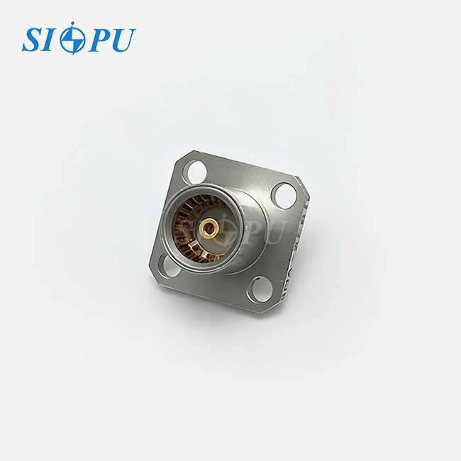
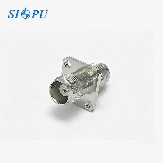
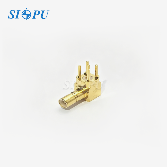
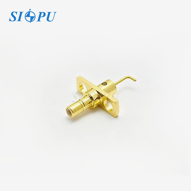
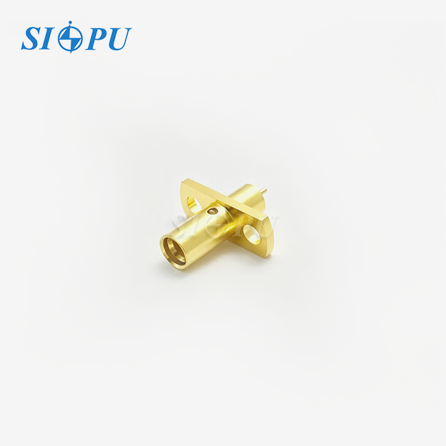
The name consists of three components. The word “female” refers to the recessed center contact that is meant to accept a mating male pin. "Right-angle" signifies that the cable leaves the mating face at a 90 degree angle. This means that the wire goes along the mounting board rather than shooting straight out from it. A flange mount is a plate with two or four holes that may be used to firmly attach the connection body to the chassis panel.
Core Electrical Specifications
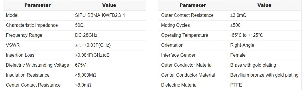
This device will function from DC to 28 GHz, a wide frequency range that is ideal for most 5G backhaul, millimeter-wave radar and wideband test requirements. The insertion loss is stated as ≤0.08√F(GHz) dB. The VSWR is given as ≤1.1 + 0.03F(GHz). The nominal impedance is 50 Ω, the dielectric withstands up to 675 V and the insulation resistance is more than 5,000 MΩ. All of these values are particularly essential when you are using high density backplane arrays.
Why the Right-Angle Flange Design Solves Real Problems
In compact equipment racks, the room for the cables that travel up and down is frequently the first to run out. Because of the right-angle exit, the needed rear clearance is lowered, which enables the boards slot closer together. The flange offers a robust mechanical anchor that helps prevent connection movement during temperature variations from -65 °C to +125 °C or mechanical vibration. The connection is rated for at least 500 mating cycles, and the spring characteristics of the gold-plated beryllium copper core contacts are intended to ensure reliable electrical contact over the stated service life.
Comparing the SBMA Right-Angle Flange Connector With Alternatives
SBMA vs. SMA
You'll need a torque wrench for SMA connections with threads. A 64-port backplane can be difficult to assemble using threaded connections because each port must be aligned and tightened individually. For blind-mate backplane arrays, the SBMA slide-on interface is suitable because it allows the components to mate through straight axial movement. By comparison, an SMA connector typically supports frequencies up to 18 GHz in standard configurations, while precision versions can reach 26.5 GHz. The SBMA female right-angle flange mount connector can operate up to 28 GHz on the SIPU platform, making it suitable for applications requiring both blind-mate convenience and wider frequency coverage.
SBMA vs. SMB and SMP
SMB connections are good up to 4 GHz, which is adequate for low frequency work, but not microwave operations. SBMA connections are related to SMP connectors. Both can be slipped on, however the SMP plugs are smaller and their mechanical durability and mating-cycle rating may vary with their design. SMP is good for establishing PCB parts connections. The SBMA female right-angle flange mount form factor is a good alternative for greater chassis-level integration and mechanical support due to the more robust mounting framework offered by the flange.
Straight vs. Right-Angle Body Orientation
A straight connection needs appropriate room behind the panel since the cable runs straight away from the mating face. With the right angle variant, the cable exits parallel to the mounting board. This setup is ideal for security and communications enclosures when back clearance is restricted. In many circumstances, the right-angle body is the preferred style when there isn’t enough room behind the connection for a straight cable assembly.
Procurement Considerations for the SBMA Female Right-Angle Flange Mount Connector
Evaluating Supplier Credibility
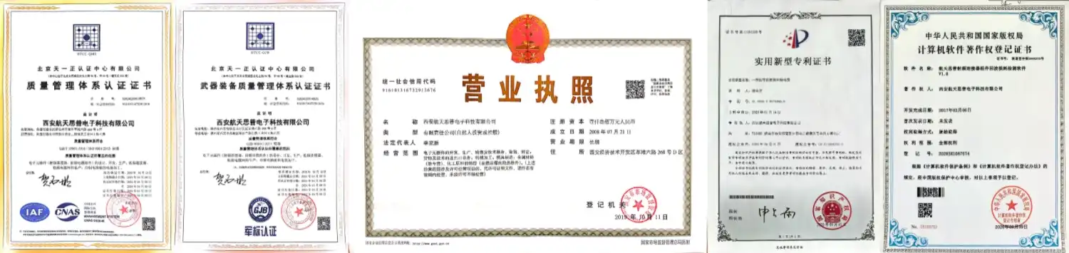
ISO 9001 certification. Batch test results for contact resistance center ≤8.0 mΩ, outside ≤3.0 mΩ. XRF plating confirmation. Companies like Amphenol, TE Connectivity, they set the benchmark." And a reputable alternative supplier should be able to offer you the same papers. SIPU is ISO 9001 certified and tests each batch for dielectric withstand performance and insulation resistance.
Lead Time, Pricing, and Inventory Strategy
For components purchased for three to six month projects (like telecom OEM programs) standard stock availability is sometimes more significant than the unit pricing. SIPU ships basic setups from its Xi'an plant in 72 hours. There are a number of separate lines that run priorities for unique mechanical models. You may request a mixed-sample pricing sheet to try more than one SKU before committing to a production volume. This allows you to compare the SBMA female right angle flange mount connection with various component numbers.
Customization and Compliance
It is crucial to make sure that the supplier is able to implement the adjustments you want. For example, if your system requires special flange hole designs, cable terminations for RG405 or similar cable, or varied plating thickness, supply the dimensions and technical drawings. Depending on the product and application, there are regulations for items entering the EU and U.S. markets, such as RoHS, REACH, CE, IEC and UL criteria. Before you submit your first sample purchase, make sure you have written agreement on all relevant compliance requirements. SIPU said the SIPU-SBMA-KWFB2G-1 line passes all five requirements.
Advantages and Practical Applications
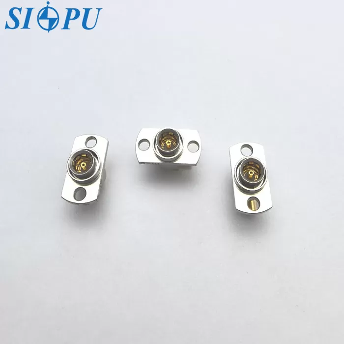
The SBMA female right-angle flange mount connector can be used in a lot of different ways, from defense electronics to dense telecom infrastructure. When it comes to performance, these are the main advantages of this device:
- Wide frequency coverage: DC to 28 GHz makes this connector usable across 5G NR bands, S-band and X-band radar, and broadband test equipment without needing separate part families.
- Blind-mate reliability: The slide-on female contact accommodates axial and radial float, allowing automated or tool-free mating in multi-port backplane assemblies—cutting board-swap time substantially.
- Temperature range: The −65 °C to +125 °C operating window covers avionics bay temperatures, outdoor telecom cabinets, and military vehicle electronics.
- Low-loss PTFE dielectric: PTFE minimizes signal loss at millimeter-wave frequencies and resists moisture absorption, which matters in environments with condensation risk.
- Gold-plated BeCu contacts: Beryllium copper provides the spring force needed to maintain reliable contact after repeated insertions; gold plating helps prevent contact-resistance increases caused by surface oxidation and wear.
Most telecom and defense OEM engineers worry about three things: how well the shielding works, how consistent the VSWR is across batches, and how repeatable the dimensions are across batches. These benefits directly address all three of these issues. Many blind-mate connections have to be made at the same time between the antenna face and the processing backplane in phased-array radar T/R modules, for instance. If the shapes of the connectors are not consistent, the beams may not point correctly.
How to Choose the Right SBMA Female Right-Angle Flange Mount Connector
Define Your Electrical Requirements First
Begin with the frequency range, the conventional 50-Ω impedance, and the VSWR budget that your system link analysis tells you. The connection is designed to work up to 28 GHz, so if you want to add additional bands later you won't have to rebuild the whole system. Before utilising a connection, be sure you know how much power it can withstand at the frequencies you intend to utilise. Power handling is frequency, VSWR, and temperature dependent and should be checked with the supplier's specs.
Confirm Mechanical and Environmental Fit
The flange hole design must conform to the chassis drawing. The cable should be RG405 or other comparable semi rigid cable with a suitable termination design for the connection. The operational temperature range should cover worst-case scenarios. If the product is going into a defence application and has to fulfil MIL-STD-810 vibration criteria, then you should ask the supplier for the appropriate vibration test results.
Run a Structured Sample Evaluation
Request a sample set that includes products from at least two separate manufacturing runs. Use a milliohm meter to measure the contact resistance of each sample. Look examine the plating very closely under a microscope. Before doing electrical measurements, mate and unmate the connections at least 20 times. This procedure helps to ensure that the plating quality and electrical performance are consistent from production run to production run before being employed in production.
Conclusion
You need to know what the RF connection needs to do electrically and physically before you can choose it. There are space restrictions on dense backplanes, frequency requirements in modern microwave systems, and mechanical stresses on platforms that are vibrating. The SBMA female right-angle flange mount connector can address these requirements. You can select a connector that meets your project requirements by confirming that its electrical and mechanical specifications match your system needs and that the provider follows a strict sample evaluation and approval process.
FAQ
1. What frequency range does the SBMA female right-angle flange mount connector support?
The SIPU-SBMA-KWFB2G-1 covers DC to 28 GHz, making it suitable for 5G backhaul, radar, and wideband test applications.
2. How many mating cycles is this connector rated for?
The connector is rated for ≥500 mating cycles under normal operating conditions.
3. What cable type is compatible?
It is compatible with RG405 and equivalent semi-rigid cables.
4. What does the flange mount provide beyond mechanical support?
The flange anchor prevents connector movement during vibration or thermal cycling, protecting the RF interface from impedance shifts caused by micro-movement.
5. Is the connector compliant with RoHS and REACH?
Yes. SIPU declares RoHS, REACH, CE, IEC, and UL compliance for this product series.
6. What operating temperature range does it cover?
It operates reliably from −65 °C to +125 °C, covering avionics, defense, and outdoor telecom environments.
Request Your SBMA Female Right-Angle Flange Mount Connector Sample From SIPU
RF connectors made by SIPU RF Technology in Xi'an have been used by OEMs in the defense, aerospace, and telecom industries for more than 25 years. In most cases, the SIPU-SBMA-KWFB2G-1 SBMA female right-angle flange mount connector is sent out within 72 hours. It is also possible for specialized production lines to handle custom configurations. To get samples, prices, or technical details from a trusted supplier of SBMA female right-angle flange mount connectors, email our team at info@sipu-rf.com or visit sipuconn.com.
References
1. IEEE Standard 287-2007 – IEEE Standard for Precision Coaxial Connectors (DC to 110 GHz), IEEE, 2007.
2. RF and Microwave Engineering: Fundamentals of Wireless Communications, Frank Gustrau, Wiley, 2012.
3. Microwave Engineering, David M. Pozar, 4th Edition, Wiley, 2011.
4. MIL-PRF-31031 – Performance Specification: Connectors, Radio Frequency (RF), General Specification for, U.S. Department of Defense, 2002.
5. High-Speed Signal Propagation: Advanced Black Magic, Howard W. Johnson & Martin Graham, Prentice Hall, 2003.
6. IEC 61169-1 – Radio-Frequency Connectors – Part 1: General Requirements and Measuring Methods, IEC, 2013.
Contact us directly for customized solutions, quotations and long-term strategic cooperation.